


Prometheus CPU User Manual V1.44 Page 46
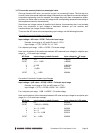
Single-ended / Differential Inputs
Prometheus can accept both single-ended and differential inputs. A single-ended input uses 2
wires, input and ground. The measured input voltage is the difference between these two wires. A
differential input uses 3 wires: input +, input -, and ground. The measured input voltage is the
difference between the + and - inputs.
Differential inputs are frequently used when the grounds of the input device and the measurement
device (Prometheus) are at different voltages, or when a low-level signal is being measured that
has its own ground wire. A differential input also has higher noise immunity than a single-ended
input, since most noise affects both + and – input wires equally, so the noise will be canceled out
in the measurement. The disadvantage of differential inputs is that only half as many are
available, since two input pins are required to produce a single differential input. Prometheus can
be configured for either 16 single-ended inputs or 8 differential inputs.
If you have a combination of single-ended and differential input signals, select differential mode.
Then to measure the single-ended signals, connect the signal to the + input and connect analog
ground to the - input.
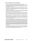
WARNING: The maximum range of voltages that can be applied to an analog input on
Prometheus without damage is ±35V. If you connect the analog inputs on Prometheus to a circuit
whose ground potential plus maximum signal voltage exceeds ±35V, the analog input circuit may
be damaged. Check the ground difference between the input source and Prometheus before
connecting analog input signals.
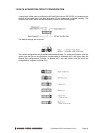
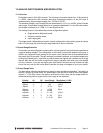
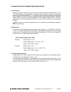
Unipolar / Bipolar Inputs
The analog inputs can be configured for can be configured for unipolar (positive input voltages
only) or bipolar (both negative and positive input voltages). For unipolar inputs, install a jumper
as shown. For bipolar inputs, leave the jumper out.
Analog Output Configuration
The 4 analog outputs can also be configured for unipolar (positive voltages only) or bipolar (both
negative and positive output voltages). In unipolar mode, the outputs range between 0-10V. In
bipolar mode, the outputs range between ±10V.
When the board powers up or is reset, the analog outputs are also reset. The D/A reset method
is selected with a jumper on J13. If the jumper is in, the outputs will reset to the bottom of their
range (called zero-scale). If the jumper is out, the outputs will reset to the middle of their range
(mid-scale). Normally the D/A is configured to power up to 0V, so that when the power is turned
on the device connected to the analog output doesn’t see a step change in voltage. Therefore, for
unipolar mode normally the outputs should be configured for zero-scale reset, and for bipolar
mode the outputs should be configured for mid-scale reset, since 0V is halfway between -10V and
+10V for the ±10V range.