


Prometheus CPU User Manual V1.44 Page 59
20. COUNTER/TIMER OPERATION
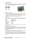
Prometheus model PR-Z32-EA contains two counter/timers that provide various timing functions
on the board for A/D timing and user functions. These counters are controlled with registers in the
on-board data acquisition controller FPGA. See pages 38 and 43 for information on the
counter/timer control register bits and how to perform various functions using these counters.
20.1 Counter 0 – A/D Sample Control
The first counter, Counter 0, is a 24-bit “divide-by-n” counter used for controlling A/D sampling.
The counter has a clock input, a gate input, and an output. The input is a 10MHz or 1MHz clock
provided on the board and selected with bit CKFRQ0 in Base + 4 bit 5. The gate is an optional
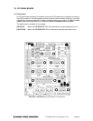
signal that can be input on pin 21 of the I/O header J14 when DIOCTR (Base + 11 bit 7) is 1. If
this signal is not used then the counter runs freely. The output is a positive pulse whose
frequency is equal to the input clock divided by the 24-bit divisor programmed into the counter.
The output appears on pin 24 of the I/O header when DIOCTR=1.
The counter operates by counting down from the programmed divisor value. When it reaches
zero, it outputs a positive-going pulse equal to one input clock period (100ns or 1µs, depending
on the input clock selected by CKFRQ0). It then reloads to the initial load value and repeats the
process indefinitely.
The output frequency can range from 5MHz (10MHz clock, divisor = 2) down to 0.06Hz (1MHz
clock divided by 16,777,215, or 2
24
-1). The output is fed into the A/D timing circuit and can be
selected to trigger A/D conversions when AINTE is 1 and ADCLK is 0 in Base + 4. Using the
control register at Base + 15 the counter can be loaded, cleared, enabled, and disabled, the
optional gate can be enabled and disabled, and the counter value can be latched for reading.
20.2 Counter 1 – Counting/Totalizing Functions
The second counter, Counter 1, is similar to Counter 0 except it is a 16-bit counter. It also has an
input, a gate, and an output. These signals may be user-provided on the I/O header when
DIOCTR=0 or the input may come from the on-board clock generator. When the on-board clock
generator is used, the clock frequency is either 10MHz or 100KHz as determined by control bit
CKFRQ1 in Base + 4.
The output is a positive-going pulse that appears on pin 26 of the I/O header. The output pulse
occurs when the counter reaches zero. When the counter reaches zero it will reload and start
over on the next clock pulse. The output stays high the entire time the counter is at zero, i.e. from
the input pulse that causes the counter to reach zero until the input pulse that causes the counter
to reload.
When DIOCTR=0, Counter 1 operates as follows: It counts positive edges of the signal on pin 23
on the I/O header. The gate is provided on pin 22. If it is high then the counter will count, and if it
is low the counter will hold its value and ignore input pulses. This pin has a pull-up so the counter
can operate without any external gate signal.
NOTE: When counting external pulses, Counter 1 will only update its read register every 4th
pulse. This behavior is due to the synchronous design of the counter having to contend with the
asynchronous input pulses. The count register contents are correct on the 4th pulse but will
remain static until 4 more pulses occur on the input.
When DIOCTR=1, Counter 1 operates as follows: It takes its input from the on-board clock
generator based on the value of the CKFRQ1 bit in Base + 4. There is no gating and the counter
runs continuously.
Counter 1 may be used as either a pulse generator or a totalizer/counter. In pulse generator
mode the output signal on pin 26 is of interest. In totalizer/counter mode the counter value is of
interest and may be read by first latching the value and then reading it.