


Prometheus CPU User Manual V1.44 Page 37
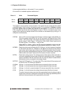
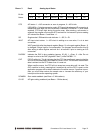
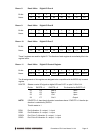
Base + 3 Read Analog Input Status
Bit No. 7 6 5 4 3 2 1 0
Name STS SD WAIT DACBSY OVF SCANEN G1 G0
STS A/D status. 1 = A/D conversion or scan in progress, 0 = A/D is idle.
If SCANEN = 0 (single conversion mode), STS goes high when an A/D conversion is
started and stays high until the conversion is finished. If SCANEN = 1 (scan mode
enabled), STS stays high during the entire scan. After starting a conversion in
software, the program must monitor STS and wait for it to become 0 prior to reading
A/D values from Base + 0 and Base + 1.
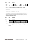
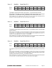
SD Single-ended / Differential mode indicator. 1 = SE, 0 = DI.
WAIT A/D input circuit status. 1 = A/D circuit is settling on a new value, 0 = ok to start
conversion.
WAIT goes high after the channel register (Base + 2) or the gain register (Base + 3)
is changed. It stays high for 9 microseconds. The program should monitor this bit
after writing to either register and wait for it to become 0 prior to starting an A/D
conversion.
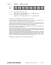
DACBSY Indicates the DAC is busy updating (approx. 30 µS). 1 = Busy, 0 = Idle. Do not
attempt to write to the DAC (registers 6 and 7) while DACBSY = 1.
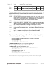
OVF FIFO Overflow bit. This bit indicates that the FIFO has overflowed, meaning that the
A/D circuit has attempted to write data to it when it is full. This condition occurs when
data is written into the FIFO faster than it is read out.
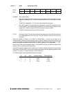
When overflow occurs, the FIFO will not accept any more data until it is reset. The
OVF condition is sticky, meaning that it remains true until the FIFO is reset, so the
application program will be able to determine if overflow occurs. If overflow occurs,
then you must either reduce the sample rate or increase the efficiency of your
interrupt routine and/or operating system.
SCANEN Scan mode readback (see Base + 3 Write above).
G1-G0 A/D gain setting readback (see Base + 3 Write above).