


96 RabbitCore RCM4000
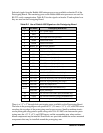
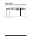
Table B-1 lists the electrical, mechanical, and environmental specifications for the Proto-
typing Board.
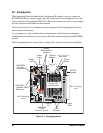
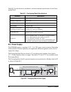
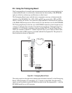
B.3 Power Supply
The RCM4000 requires a regulated 3.0 V – 3.6 V DC power source to operate. Depending
on the amount of current required by the application, different regulators can be used to
supply this voltage.
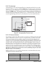
The Prototyping Board has an onboard +5 V switching power regulator from which a
+3.3 V linear regulator draws its supply. Thus both +5 V and +3.3 V are available on the
Prototyping Board.
The Prototyping Board itself is protected against reverse polarity by a Shottky diode at D2
as shown in Figure B-3.
Figure B-3. Prototyping Board Power Supply
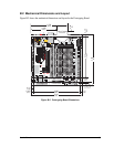
Table B-1. Prototyping Board Specifications
Parameter Specification
Board Size 3.80" × 3.80" × 0.48" (97 mm × 97 mm × 12 mm)
Operating Temperature 0°C to +70°C
Humidity 5% to 95%, noncondensing
Input Voltage 8 V to 24 V DC
Maximum Current Draw
(including user-added circuits)
800 mA max. for +3.3 V supply,
1 A total +3.3 V and +5 V combined
Prototyping Area
1.3" × 2.0" (33 mm × 50 mm) throughhole, 0.1" spacing,
additional space for SMT components
Connectors
One 2 × 25 header socket, 1.27 mm pitch, to accept RCM4000
One 1 × 3 IDC header for power-supply connection
One 2 × 5 IDC RS-232 header, 0.1" pitch
Two unstuffed header locations for analog and RCM4000 signals
25 unstuffed 2-pin header locations for optional configurations
LINEAR POWER
REGULATOR
POWER
IN
J1
10 µF
LM1117
U1
+3.3 V
3
1
2
1
2
3
DL4003
D2
47 µF
330 µF
+5 V
L1
C5
330 µH
D1
B140
SWITCHING POWER REGULATOR
DCIN
U2
LM2575
C6
C2
10 µF
C4
JP1
JP2