


User’s Manual 11
2.2.4 Connect Power
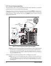
Once all the other connections have been made, you can connect power to the Prototyping
Board. Connect the AC adapter to 3-pin header J1 on the Prototyping Board as shown in
Figure 4 above. The connector may be attached either way as long as it is not offset to one
side—the center pin of J1 is always connected to the positive terminal, and either edge pin
is ground.
Plug in the AC adapter. The PWR LED on the Prototyping Board next to the power con-
nector at J1 should light up. The RCM4000 and the Prototyping Board are now ready to be
used.
NOTE: A RESET button is provided on the Prototyping Board next to the battery holder
to allow a hardware reset without disconnecting power.
Other Power-Supplies
Development Kits sold outside North America include a header connector that may be
used to connect your power supply to 3-pin header J1 on the Prototyping Board. The
power supply should deliver 8 V–30 V DC at 8 W.