


User’s Manual 33
4.3 Programming Cable
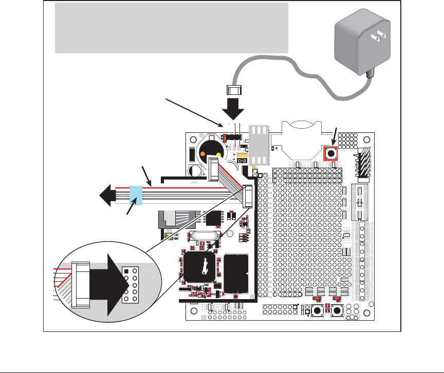
The programming cable is used to connect the programming port of the RCM4000 to a PC
serial COM port. The programming cable converts the RS-232 voltage levels used by the
PC serial port to the CMOS voltage levels used by the Rabbit 4000.
When the
PROG connector on the programming cable is connected to the programming
port on the RCM4000, programs can be downloaded and debugged over the serial interface.
The DIAG connector of the programming cable may be used on header J1 of the RCM4000
with the RCM4000 operating in the Run Mode. This allows the programming port to be
used as a regular serial port.
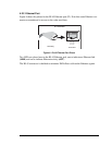
4.3.1 Changing Between Program Mode and Run Mode
The RCM4000 is automatically in Program Mode when the PROG connector on the pro-
gramming cable is attached, and is automatically in Run Mode when no programming
cable is attached. When the Rabbit 4000 is reset, the operating mode is determined by the
status of the SMODE pins. When the programming cable’s PROG connector is attached,
the SMODE pins are pulled high, placing the Rabbit 4000 in the Program Mode. When the
programming cable’s PROG connector is not attached, the SMODE pins are pulled low,
causing the Rabbit 4000 to operate in the Run Mode.
Figure 9. Switching Between Program Mode and Run Mode
D1
R1
PWR
DS1
GND
J1
U1
C1
GND
C2
JP1
C3
D2
JP2
C4
+3.3 V
J2
R2
BT1
1
S1
RESET
RXD TXD
TXC RXC
GND
J4
UX29
RX81
RX87
CX41
RX83
RX11
CX39
UX30
UX10
UX12
UX14
UX16
RX79
CX29
CX17
RX67
UX45
RX85
GND
GND
GND
1
R24
R22
R21
R23
CX23
RX77
1
R27
R28
JP25
CX25
RX75
RX73
CX27
DS3
S3S2
DS2
J3
UX49
UX4
UX47
+5 V
GND
+3.3 V
RCM1
U2
/RST_OUT
/IOWR
VBAT
EXT
PA1
PA3
PA5
PA7
PB1
PB3
PB5
PB7
PC1
PC3
PC5
PC7
PE1
PE3
PE5
PE7
PD1
LN1
PD3
LN3
PD5
LN5
PD7
LN7
VREF
GND
/IORD
/RST_IN
PA0
PA2
PA4
PA6
PB0
PB2
PB4
PB6
PC0
PC2
PC4
PC6
PE0
PE2
PE4
PE6
PD0
LN0
PD2
LN2
PD4
LN4
PD6
LN6
CVT
AGND
JP24
JP23
C14
C12
C10
C8
C7
C9
C11
C13
R10
R8
R6
R4
R3
R5
R7
R20
R18
R16
R14
R13
R15
R17
R29
JP11
JP15
JP19
JP21
JP22
JP20
JP17
JP13
R19
R9
RX57
RX55
RX97
RX49
UX33UX31
RX89
UX3
UX37 UX42
UX41
RX63
RX65
RX61
RX59
R26
R25
Q1
C15
C19 C20
U3
C18
C17
JP16
JP6
JP5
JP12
JP4
JP3
JP14
JP8
JP7
JP18
JP9
JP10
C16
L1
C6
C5
AGND
CVT
LN6IN
LN4IN
LN2IN
LN0IN
VREF
LN7IN
LN5IN
LN3IN
LN1IN
AGND
AGND
R11
R12
RX47
RX43
R34
C8
C7
C9
C12
C14
L6
L7
C15
C11
L5
L4
R20
J2
C41
R35
DS1
DS2
R37
R36
ACT
LINK
C72
Y3
C71
U17
C66
R46
U18
R47
C53
C54
C52
C51
C50
C49
C47
C48
U7
C42
C43
U6
C34
C35
Y1
U5
R25
C33
R24
C20
Q1
T1
C18
L3
R7
R6
L2
C16
C13
L9
L8
R5
R4
R3
R1
R2
R8
R51
C10
U1
R9
R10
JP1
JP3
JP2
U3
C22
C23
RP2
R43
D1
R27
R28
JP4
R33
R32
R31
Y2
R48
C55
C56
C46
C45
C44
U9
R30
C38
U8
C36
R26
C32
C30
C31
R29
C29
C28
C26
C27
C24
C25
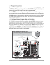
J1
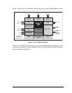
RESET
3-pin
power connector
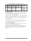
J1
Colored
edge
To
PC COM port
Blue
shrink wrap
PROG
DIAG
Programming
Cable
PROG
J1
RESET RCM4000 when changing mode:
Press RESET button (if using Prototyping Board),
OR
Remove, then reapply power
after removing or attaching programming cable.