


User’s Manual 89
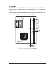
A.6 Jumper Configurations
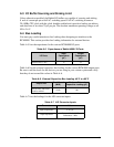
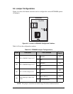
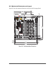
Figure A-6 shows the header locations used to configure the various RCM4000 options
via jumpers.
Figure A-6. Location of RCM4000 Configurable Positions
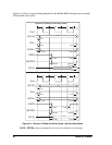
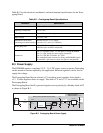
Table A-9 lists the configuration options.
NOTE: The jumper connections are made using 0 Ω surface-mounted resistors.
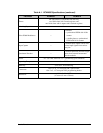
Table A-9. RCM4000 Jumper Configurations
Header Description Pins Connected
Factory
Default
JP1 PE6 or SMODE1 Output on J3
1–2 SMODE1
×
2–3 PE6
JP2 PE5 or SMODE0 Output on J3
1–2 SMODE0
×
2–3 PE5
JP3 PE7 or STATUS Output on J3
1–2 STATUS
×
2–3 PE7
JP4
Battery Backup for Real-Time
Clock
1–2 Battery Backup
×
2–3 No Battery Backup
JP4
JP1
JP2
JP3
RCM4000
Top Side