


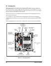


100 RabbitCore RCM4000
B.4.3 Analog Features (RCM4000 only)
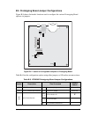
The Prototyping Board has typical support circuitry installed to complement the ADS7870
A/D converter on the RCM4000 module (the A/D converter is not available on the
RCM4010 module).
B.4.3.1 A/D Converter Inputs
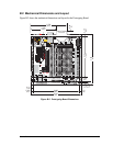
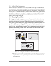
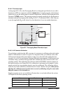
Figure B-6 shows a pair of A/D converter input circuits. The resistors form an approx. 9:1
attenuator, and the capacitor filters noise pulses from the A/D converter input. The 10 kΩ
inline jumpers allow other configurations (see Table B-6) and provide digital isolation.
Figure B-6. A/D Converter Inputs
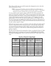
The A/D converter chip can make either single-ended or differential measurements
depending on the value of the opmode parameter in the software function call. Adjacent
A/D converter inputs are paired to make differential measurements. The default setup on
the Prototyping Board is to measure only positive voltages for the ranges listed in Table B-3.
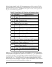
Table B-3. Positive A/D Converter Input Voltage Ranges
Min. Voltage
(V)
Max. Voltage
(with prescaler)
(V)
A/D Converter
Gain
mV per Tick
0.0 +22.528 1 11
0.0 +11.264 2 5.5
0.0 +5.632 4 2.75
0.0 +4.506 5 2.20
0.0 +2.816 8 1.375
0.0 +2.253 10 1.100
0.0 +1.408 16 0.688
0.0 +1.126 20 0.550
100 kW
LN0_IN
AGND
LN1_IN
ADC
BVREF =
2.048 V
100 kW
2.2 nF
10 kW
10 kW
2.2 nF
ADC
(RCM4100)
JP23/JP24
1
3
Inline jumpers are
10 kW resistors