


User’s Manual 107
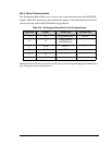
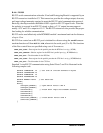
NOTE: Jumper connections JP3–JP10, JP12, JP14, JP16, JP18, JP23, and JP24 are made
using 0 Ω surface-mounted resistors. Jumper connections JP11, JP13, JP15, JP17, and
JP19–JP22 are made using 10 kΩ surface-mounted resistors.
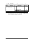
JP23 LN4_IN–LN6_IN
1–2 Tied to analog ground
×
2–3 Tied to VREF
JP24 LN0_IN–LN3_IN
1–2 Tied to analog ground
×
2–3 Tied to VREF
JP25 Thermistor Location 1–2 n.c.
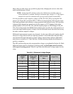
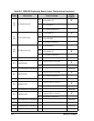
Table B-6. RCM3400 Prototyping Board Jumper Configurations (continued)
Header Description Pins Connected
Factory
Default