


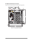


98 RabbitCore RCM4000
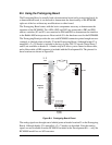
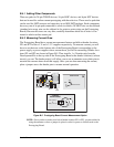
Selected signals from the Rabbit 4000 microprocessor are available on header J2 of the
Prototyping Board. The remaining ports on the Rabbit 4000 microprocessor are used for
RS-232 serial communication. Table B-2 lists the signals on header J2 and explains how
they are used on the Prototyping Board.
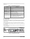
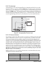
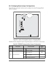
There is a 1.3" × 2" through-hole prototyping space available on the Prototyping Board.
The holes in the prototyping area are spaced at 0.1" (2.5 mm).
+3.3 V, +5 V, and GND traces
run along the top edge of the prototyping area for easy access.
Small to medium circuits
can be prototyped using point-
to-point wiring with 20 to 30 AWG wire between the proto-
typing area, the
+3.3 V, +5 V, and GND traces,
and the surrounding area where surface-
mount components may be installed.
Small holes are provided around the surface-mounted
components that may be installed around the prototyping area.
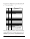
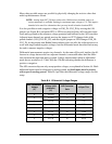
Table B-2. Use of Rabbit 4000 Signals on the Prototyping Board
Pin Pin Name Prototyping Board Use
1 +3.3 V +3.3 V power supply
2 GND
3 /RST_OUT Reset output from reset generator
4 /IORD External read strobe
5 /IOWR External write strobe
6 /RESET_IN Input to reset generator
8–15 PA0–PA7 Output, pulled high
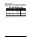
16 PB0 CLKB (used by A/D converter RCM4000 only)
17 PB1 Programming port CLKA
18 PB2 LED DS2 (normally high/off)
19 PB3 LED DS3 (normally high/off)
20 PB4 Switch S2 (normally open/pulled up)
21 PB5 Switch S3 (normally open/pulled up)
22–23 PB6–PB7 Output, pulled high
24–25 PC0–PC1 Serial Port D (RS-232, header J4) (high)
26–27 PC2–PC3 Serial Port C (RS-232, header J4) (high)
28–29 PC4–PC5 Serial Port B (used by A/D converter RCM4000 only)
30–31 PC6–PC7 Serial Port A (programming port) (high)
32–39 PE0–PE7 Parallel I/O, Output, I0–I7
40–47
LN0–LN7 A/D converter inputs (RCM4000 only)
PD0–PD7 Output, pulled high
48 CONVERT A/D converter CONVERT input (RCM4000 only)
49 VREF A/D converter reference voltage (RCM4000 only)
50 AGND A/D converter ground (RCM4000 only)