


COMSPHERE 3900 Series Modems
14-12 September 1998 3910-A2-GN32-40
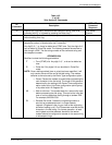
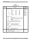
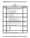
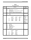
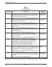
Table 14-2
(8 of 10)
391x Series AT Commands
AT
Command
DCP LCD
Command
Sequence
Description
&Vn View Configuration Options. Displays each configuration group within the
Active (Operating), Active (Saved), Customer 1, and Customer 2
configuration areas as well as the telephone numbers stores in directory
locations 1–24.
&V0 Active (Operating) configuration options.
&V1 Active (Saved) configuration options.
&V2 Customer 1 configuration options.
&V3 Customer 2 configuration options.
&V4 Directory locations 1–24.
None
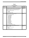
&Wn Write (Save to Memory). Saves the current configuration options in
Active (Operating) to one of three configuration areas:
&W0 Saved to Active(Save).
&W1 Saved to Customer 1.
&W2 Saved to Customer 2.
Configure\Save
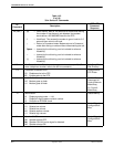
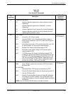
&Xn Transmit Clock Source.
&X0 Internal. Modem provides transmit clock source for
synchronous data (Pin 15).
&X1 External. Modem derives external transmit clock source
provided on Pin 24 for synchronous data.
&X2 Receive Clock Loop. Modem derives transmit clock source
from receive signal for synchronous data (Pin 17).
Configure\Edit\
DTE Interface
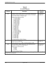
&Zn=x Store Telephone Numbers. Modem saves the telephone numbers and
dial command modifiers (if any) entered for x (up to 40 characters in
length) in Directory Location n (1–24). For example, the command
AT&Z1 = 5551234 stores the telephone number 555-1234 into directory
location 1.
To clear a telephone number from a memory location, issue the &Zn=x
command without entering a telephone number.
Call Setup\
Change
Directory
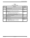
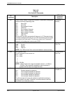
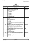
\An Maximum Frame Size.
\A0 64 bytes.
\A1 128 bytes.
\A2 192 bytes.
\A3 256 bytes.
\A4 32 bytes.
\A5 16 bytes.
Configure\Edit\
V42/MNP/Buffer
\Cn Error Control Negotiate Buffer.
\C0 Disable.
\C1 Enable.
\C2 Disables and switches modem to Buffer mode.
Configure\Edit\
V42/MNP/Buffer