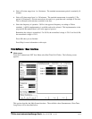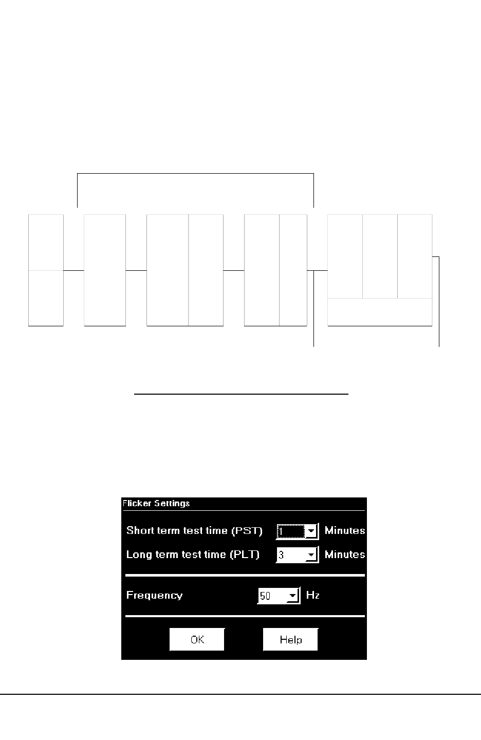
Measurement Procedure
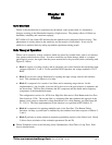
1. Original Signal with amplitude variations.
2. Square demodulator.
3. Weighted filter.
4. Low pass filter 1
st
order.
5. Statistical computing.
Q
Data available
Pst, Pst Max, Pst Min values for long term recording
Plt, Plt Max, Plt Min values for long term recording
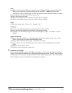
Figure 12.1: Simulation of Eye Brain Response
12.3:
Setup
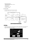
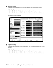
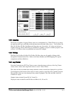
Initially the user must set up several parameters to properly configure Flicker. Using Communicator
EXT, from the Icon Menu select Edit Device Profile. From the Device Profile, select Flicker
Settings. The following screen will appear:
Electro Industries/GaugeTech
Doc # E107706 V1.25 12-3
Block 1 Block 2 Block 3
Voltage
Detector
and Gain
Control
Input
Voltage
Adaptor
Square
Law
Demodulator
High Pass
Filter
(DC
Removal)
Low
Pass Filter
(Carrier
Removal
Weighting
Filter
Squaring
Multiplier
1st
Order
Sliding
Mean
Filter
A/D
Converter
Sampling
Rate
>50Hz
Minimum
64 level
Classifier
Output
Interface
Programming of short and
long observation periods
Block 4 Block 5
Simulation Of Eye Brain Response
Output Recording
Instantaneous Flicker in
Perceptibility Units
(Pinst)
Output and Data Display
Pst Max/Min Pst
Plt Max/Min Plt


