


4 Chapter 1 General Description
HIPULSE U UPS Single Module And “1+N” (Expandable) 160/200/300/400kVA User Manual
Operating procedures in ECO mode are the same as those described in Chapter 5 Operating Instructions, except
that the load is normally on the bypass mains, the Inverter LED is normally off, and the corresponding alarm message
Bypass mode will appear on the LCD.
Warning
In ECO mode the load is not protected against mains distortion.
1.2.5 UPS Power Switch Configuration
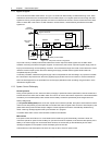
Figure 1-2 illustrates the HIPULSE U UPS module in what is known as the split bypass configuration. In the split
bypass configuration, the static bypass line is connected by a separate power switch to a dedicated bypass power
source which also feeds the maintenance bypass line. Where a separate power source is not available the bypass
(Q2) and rectifier (Q1) input supply connections would be linked together.
With the exception of the maintenance bypass switch, all the switches shown must be closed during normal UPS
operation.
1.2.6 Battery Circuit Breaker
The battery should be connected to the DC busbar through a circuit breaker fitted inside the battery cabinet — or
located adjacent to the batteries where a battery cabinet is not used. This circuit breaker is closed manually, but it
contains an undervoltage release coil which enables it to be tripped from the UPS control electronics following certain
detected faults. It also has a magnetic trip facility for overload protection.
1.2.7 Battery Temperature Compensation
HIPULSE U UPS system offers a battery temperature compensation circuit. As the temperature inside the battery
cabinet/area rises, the DC busbar voltage reduces in order to sustain the battery at its optimum charge voltage. This
must be used in conjunction with the battery temperature sensing device.
1.2.8 System Expansion
If necessary, a single module system can be expanded to cater for an increased load requirement by adding
additional modules — up to a maximum of six UPS modules can be connected in parallel.
System expansion requires a change in the SETUP of the operator control and display panel of each UPS module.
Note:
1. System expansion should be carried out only by trained service personal.
2. The individual modules connected to the system must be of the same power rating.
1.3 Operation Mode
The UPS permits operation in the following alternative modes:
Normal mode
The UPS inverter continuously supplies the critical AC load. The rectifier/charger derives power from the AC mains
input source and supplies DC power to the inverter while simultaneously float or boost charging its associated backup
battery.
Battery mode
Upon failure of the AC mains input power, the critical AC load is supplied by the inverter, which obtains power from
the battery. There is no interruption in power to the critical load upon failure or restoration of the AC mains input
power after which the Normal mode operation will continue without the necessity of user intervention.
Note: Battery start device (optional) is available for switching the UPS on into Battery (charged) mode directly during
mains failure.