


50 Chapter 6 Battery
HIPULSE U UPS Single Module And “1+N” (Expandable) 160/200/300/400kVA User Manual
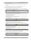
660
167
4-
Ф
13 Knockout
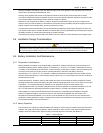
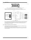
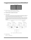
Figure 6-4 Installation hole dimensions for floor mounting of BCB box of 300/400kVA UPS (unit: mm)
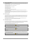
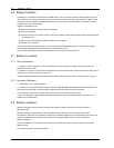
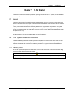
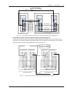
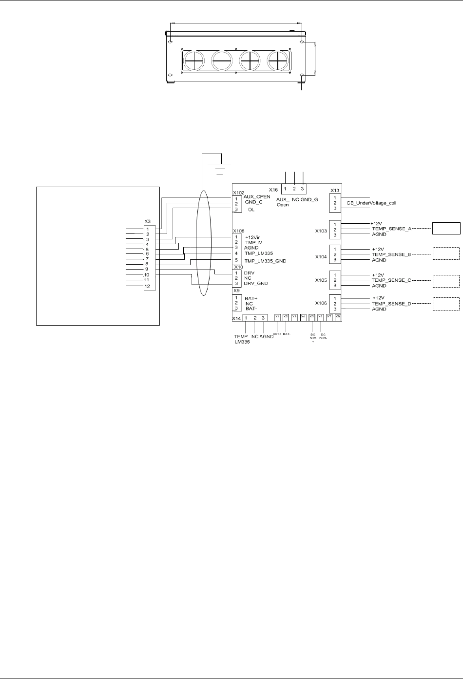
The battery circuit breaker (BCB) box contains a BCB and a BCB control board (ULK366SC1).
The BCB box is fitted as close as possible to the battery and connected to the UPS, as illustrated in Figure 6-5.
FB
GND
OL
+12V
TMP_T
GND
LM355+
LM355+ GND
DRV
DRV_ GND
NC
NC
BCB control board
UPS
TMP12Z
TMP12Z
TMP12Z
TMP12Z
BCB status feedback
BCB connection detection
Battery temperature sensing 1
Battery temperature sensing 2
BCB drive
Not connected
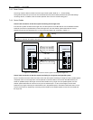
Figure 6-5 BCB box connection
Note: The control cables from the UPS to the BCB control board must be made using the accessory cable of the BCB,
which is a shielded cable located in a separate conduit to that containing the battery power cables. The cable shield
must be earthed to prevent induced noise affecting the control operation, and a separate safety earth must be
connected between the UPS and BCB box.
6.10 Battery Temperature Sensor (Optional)
A battery temperature sensor (model: TMP12Z) supplied separately from the BCB is connected with the UPS logic
through the BCB control board. For the connection, see Figure 6-5.
With this feature fitted, the nominal float voltage supplied to the battery is adjusted so as to be inversely proportional
to the ambient temperature of the battery cabinet or battery room. This prevents the battery being over charged at
high ambient temperatures.