


Chapter 7 “1+N” System 55
HIPULSE U UPS Single Module And “1+N” (Expandable) 160/200/300/400kVA User Manual
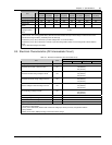
8. Check that no warning message is displayed in the top right corner of the LCD screen and the status of the LEDs
as follows:
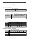
Table 7-1 LED status
LED Status
Rectifier LED Steady green
Bypass LED Off
Battery LED Off
Inverter LED Steady green
Load LED Steady green
Alarm LED Off
7.3.5 Shutdown Procedure (Complete UPS And Load Shutdown)
Refer to 5.7 Shutdown Procedure (Complete UPS And Load Shutdown).
7.4 Dual Bus System Installation Procedures
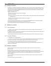
7.4.1 Cabinet Installation
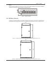
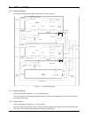
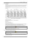
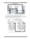
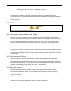
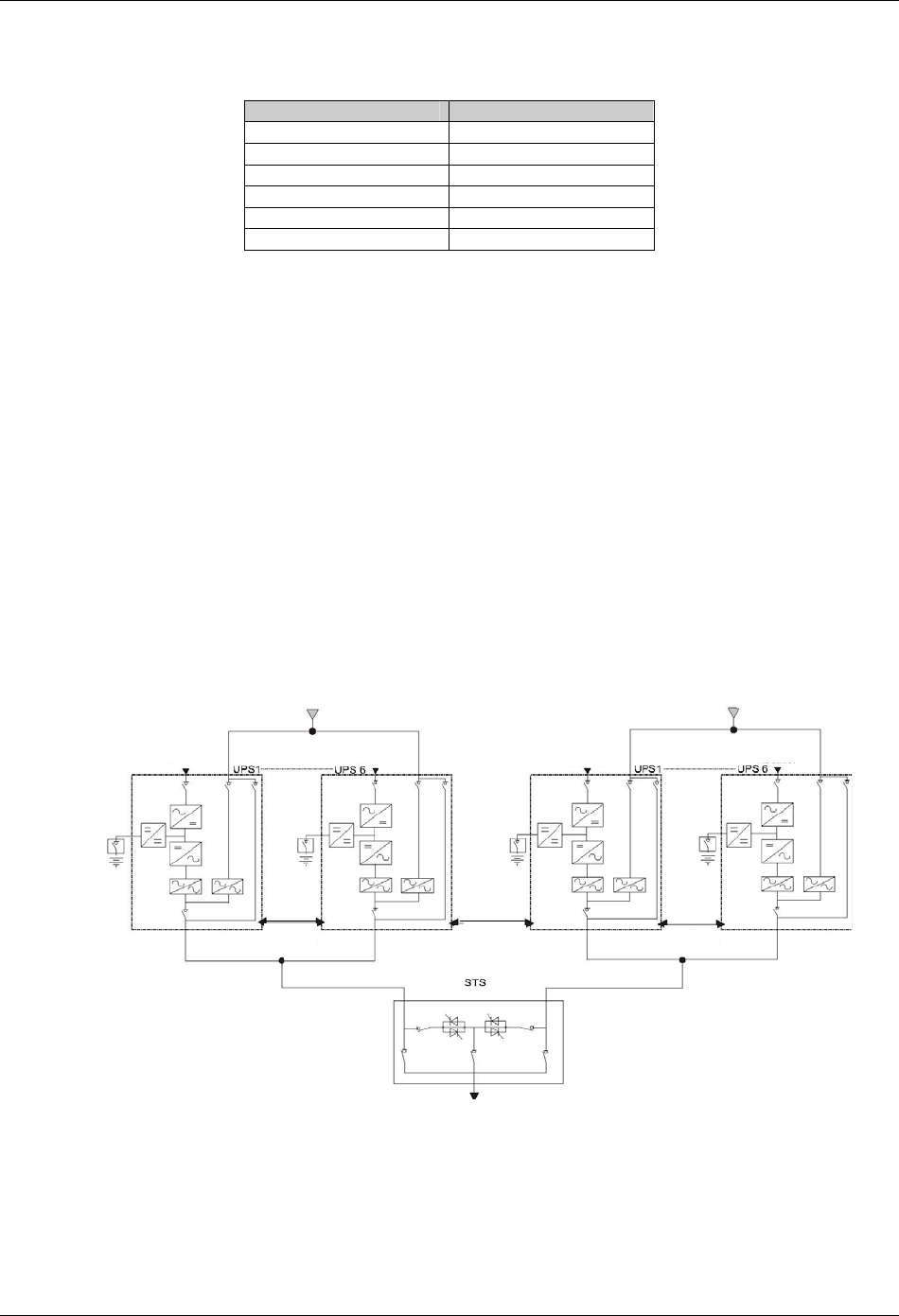
As shown in Figure 7-3, the dual bus system consists of two independent UPS configurations each consisting of one
or more UPS modules. Dual bus systems are high availability configurations suitable for loads with multiple input
terminals. For single input loads an optional static transfer switch (STS) may be added.
The objective of the dual bus system is to keep the output of two independent UPS systems (or parallel systems) in
synchronization using optional load bus synchronization (LBS) cable. One system is designated as the master; the
other is designated as the slave. The operating modes covered comprise master and or slave operating inverter or
bypass mode.
In installation, place the UPS modules side by side and interconnect as described in the following sections.
制电缆
Bypass supply
Input rectifier
Input rectifier
Parallel
cable
LBS
cable
Parallel
cable
Load
Bypass supply
Input rectifier
Input rectifier
Figure 7-3 Typical dual bus system (using STS and LBS cable)
7.4.2 Protective Devices
Refer to 3.1.6 Protective Devices.