


52 Chapter 7 “1+N” System
HIPULSE U UPS Single Module And “1+N” (Expandable) 160/200/300/400kVA User Manual
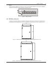
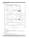
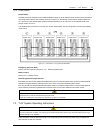
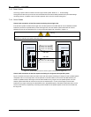
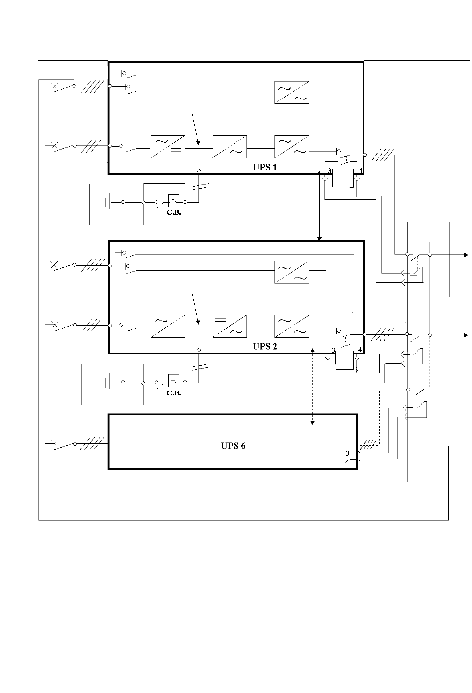
7.2.2 Cabinet Installation
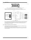
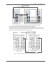
Place the UPS modules side by side and interconnect as shown in Figure 7-1.
Q5
Parallel
board
J5
Q5
并机电缆
并机电缆
Bypass
mains supply
Maintenance bypass switch Q3
Bypass switch Q2
DC bus
Rectifier Inverter Static switch
Input switch Q1
Input mains
supply
Battery 1
BCB 1
Parallel cable
Bypass
mains supply
Input mains
supply
Output
switch Q5
UPS 1
output
Ext. Sw out
UPS 2 output
Parallel
board
J5
Output
switch
Q5
Ext. Sw out
UPS 6
output
Parallel board J5
Ext. Sw out
Distribution panel
Load
Maintenance bypass switch Q3
Bypass switch Q2
DC bus
Rectifier Inverter Static switch
Input switch Q1
BCB 2
Parallel cable
Battery 2
Input
distribution
Bypass side
Bypass side
Distribution
of load
Figure 7-1 “1+N” system block diagram
7.2.3 Protective Devices
Refer to the instructions supplied in 3.1.6 Protective Devices.
Note: Use of residual current detectors (RCDs) on UPS unit inputs requires installation of a common device only on
the system bypass mains.
7.2.4 Power Cables
Refer to the instructions supplied in 3.1 Power Cabling.
Note: The length and specification of power cables including the bypass input cables and UPS output cables should
be the same. This facilitates load sharing when operating in bypass mode.