


Chapter 3 Electrical Installation 21
HIPULSE U UPS Single Module And “1+N” (Expandable) 160/200/300/400kVA User Manual
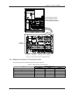
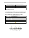
1. Battery environment, battery ground fault and generator supply detection port (J4)
The battery environment, battery ground fault and generator supply detection port is described in Table 3-3.
Table 3-3 Description of battery environment, battery ground fault and generator supply detection port
Position Name Description
J4.1 ENV
3
Battery environment detection (NC)
J4.2 BtG Battery ground fault detection (NC)
J4.3
GEN
1
,
2
On generator (NO)
J4.4
+
12V
+12V power
Note:
1. Must be configured by configuration software before becoming active.
2. When activated, the charger current can be limited, through software, to a percentage of the full charger current (0~100%).
3. Activating this feature will limit the battery charging
The UPS accepts external signaling from voltage-free (dry) contacts connected to finger-proof, push-in terminal J4.
Subject to prior software programming, the signaling is accepted by the UPS when connection between the relevant
terminal and the +12V terminal of J4 is altered. Cables connected to J4 must be segregated from power circuits (for
screening purposes), double insulated and of a typical 0.5 to 1mm
2
cross-section area for maximum runs between 25
and 50 meters, respectively.
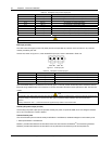
2. Maintenance bypass cabinet port (J26, J30)
J26 and J30 are the maintenance bypass cabinet (MCB) port. The ports are described in Table 3-4.
Table 3-4 Description of maintenance bypass cabinet port
Position Name Description
J26.1 T_IT
*
Input transformer overtemperature (NC)
J26.2 AUX_I (Reserved)
J26.3
+
12V
+12V power
J26.4 GND Power ground
J30.1 FUSE (Reserved)
J30.2 F_FAN Fan fail alarm (NC)
J30.3 T_OT
*
Output transformer overtemperature (NC)
J30.4 AUX_O (Reserved)
Note*: Must be configured by software before becoming active
Note
All auxiliary cables must be double insulated. Wire should be 0.5~1.5mm
2
stranded.
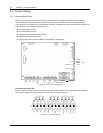
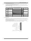
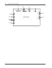
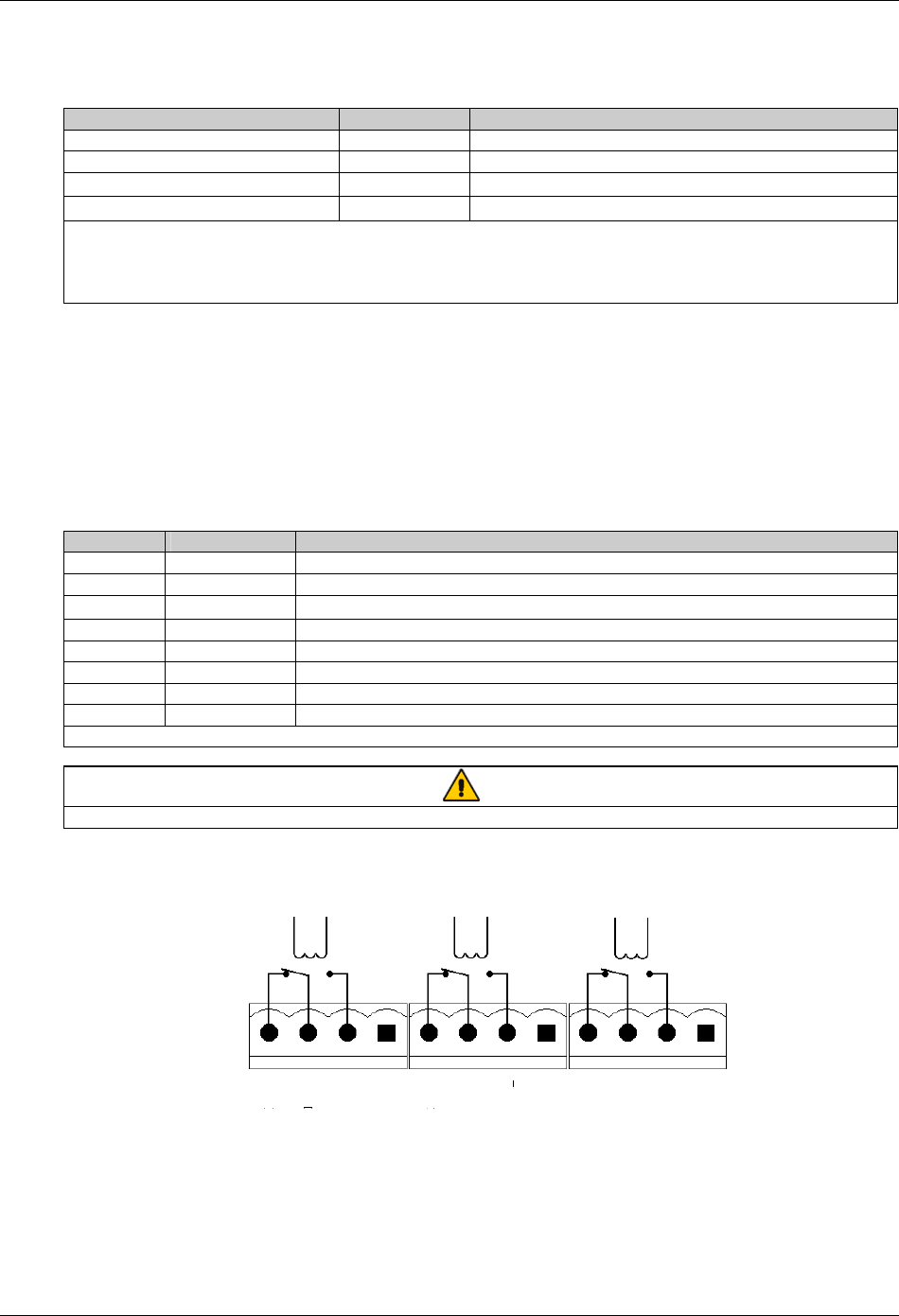
Dry contact output port (X1)
There are three output dry contact relays at the X1 slot, see Figure 3-6 and Table 3-5.
X1
J13
J21 J25
BFP_C
BFP_S
BFP_O
INV_C
INV_S
INV_O
ACF_C
ACF_S
ACF_O
Figure 3-6 Dry contact output port