


18 Chapter 3 Electrical Installation
HIPULSE U UPS Single Module And “1+N” (Expandable) 160/200/300/400kVA User Manual
6. Connect the system output cables between the output busbars (N3-U3-V3-W3 terminals) and the critical load and
tighten the connections to 13 Nm (M8 bolt), to 26 Nm (M10 bolt), and to 50 Nm (M12 bolt). ENSURE CORRECT
PHASE ROTATION.
Warning
If the load equipment will not be ready to accept power on the arrival of the commissioning engineer then ensure that the system
output cables are safely isolated at their ends.
UPS Battery Connections
7. Connect the battery cables between the UPS terminals (+/-) and its associated BCB. Connect screened auxiliary
cables from each BCB control board to the auxiliary terminal block (X3). OBSERVE THE BATTERY CABLE
POLARITY.
Warning
Do not close the BCB before the equipment has been commissioned.
8. Refit the lower protective cover.
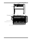
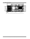
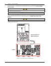
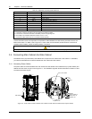
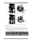
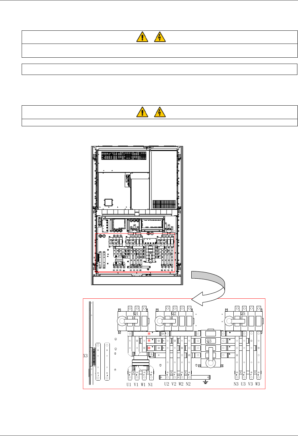
Bypass
connections
Battery
connections
Rectifier
connections
Earth
Output
connections
Auxiliary
terminal block
Note: For split bypass operation,
ensure that the busbars (*)
between the bypass input and
rectifier input are removed.
Figure 3-2 Power cable connections for 160/200kVA UPS