


Chapter 7 “1+N” System 51
HIPULSE U UPS Single Module And “1+N” (Expandable) 160/200/300/400kVA User Manual
Chapter 7 “1+N” System
This chapter introduces the installation procedures, operating instructions of the “1+N” system, and the installation of
the dual bus system, of the HIPULSE U UPS.
7.1 General
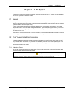
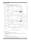
The system can comprise of up to 6 UPS modules of the same power rating and connected in parallel without the
need for a centralized mains static bypass. Instead the bypass static switches of each UPS share the load when the
system transfers to the mains bypass supply.
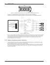
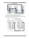
From a ‘power’ viewpoint, each module is internally identical to the ‘single module’ configuration. A “1+N” system
requires inter-module control signals to manage the load sharing, synchronizing and bypass switching. The control
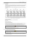
signals are connected through the parallel cables, which are multi-way ribbon cables connected between the units of
the system to form a ring.
When three or more modules are to be connected in parallel it is recommended that inductance should be inserted in
the static bypass line. This can be installed internal to the UPS as an option.
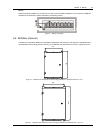
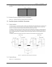
7.2 “1+N” System Installation Procedures
The basic installation procedure of a parallel system comprising two or more UPS modules is the same as that of
single module system. This section only introduces the installation procedures specific to the parallel system. The
installation of a parallel UPS must follow the installation procedure for a single UPS module with the additional
requirements detailed in this section.
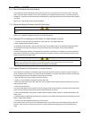
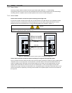
7.2.1 Preliminary Checks
Be sure that a parallel kit is present and fitted in each of the modules, and that the modules are of the same rating
and with the same software and hardware release.
Warning
To achieve coordinated operation of the modules in the parallel system, it is required to configure each module separately using
background configuration software. This must be done by Emerson service & support trained personnel.