


Chapter 5 Operating Instructions 39
HIPULSE U UPS Single Module And “1+N” (Expandable) 160/200/300/400kVA User Manual
Chapter 5 Operating Instructions
This chapter provides detailed operating notes and instructions of the HIPULSE U UPS.
5.1 Introduction
5.1.1 Notes
Important
Only after an authorized engineer has conducted the initial power-on and finished the UPS configuration is the user allowed to
operate the UPS.
No user accessable parts are located behind covers that require a tool for their removal. Only qualified service personnel are
authorised to remove such covers.
Hazardous voltages are always present at the UPS input and output terminals. If the UPS is fitted with an internal Class A filter,
the filter carries hazardous voltages too.
1. All the user controls and indicators (LED) mentioned in these procedures are identified in Chapter 4 Operator
Control And Display Panel.
2. The audible alarm may annunciate at various points in these procedures. It can be canceled at any time by
pressing the SILENCE ON/OFF button.
3. The HIPULSE U UPS system incorporates an optional automatic boost charge facility, which can be used in
systems containing conventional flooded lead-acid batteries. If this type of battery is used in your installation you may
notice that the battery charger voltage may be greater than its nominal (432Vdc for 380Vac, 446Vdc for 400Vac and
459Vdc for a 415Vac system) when the mains supply returns from a prolonged outage. This is the normal response of
the boost charge facility: the charger voltage should return to normal after a few hours.
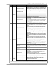
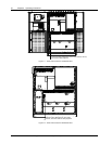
5.1.2 Power Switches
The UPS can be separated by means of power switches, mounted inside the cabinet and accessible after opening
the front door, which has a key. The location of the UPS power switches is shown in Figure 5-1 and Figure 5-2.
The UPS module power switches are:
Q1 — input switch: Connects the UPS with the mains supply.
Q2 — bypass switch: Connects the UPS with the bypass supply.
Q3 — maintenance bypass switch (padlocked): Permits supply of the load directly by the bypass line for maintenance
of the UPS module.
The internal maintenance bypass must not be used when the UPS system is comprised of more than two UPS
modules in parallel.
Q5 — output switch: Connects the output of the UPS to the load.
Note: The battery circuit breaker (BCB) is not expected inside of the UPS and should be installed in the proximity of
the respective battery.