


22 Chapter 3 Electrical Installation
HIPULSE U UPS Single Module And “1+N” (Expandable) 160/200/300/400kVA User Manual
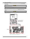
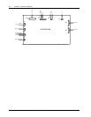
Table 3-5 Description of dry contact output port
Position Name Description
J13.2 BFP_O Bypass feedback protection relay (NO)
J13.3 BFP_S Bypass feedback protection relay center
J13.4 BFP_C Bypass feedback protection relay (NC)
J21.2 INV_O On inverter dry contact relay (NO)
J21.3 INV_S On inverter dry contact relay center
J21.4 INV_C On inverter dry contact relay (NC)
J25.2 ACF_O Main input voltage or frequency fault relay (NO)
J25.3 ACF_S Main input voltage or frequency fault relay center
J25.4 ACF_C Main input voltage or frequency fault relay (NC)
Note
All auxiliary cables must be double insulated. Wire should be 0.5~1.5mm
2
stranded.
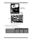
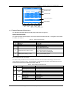
EPO input port (X2)
The UPS has an Emergency Power Off (EPO) function that operates by a button on the UPS door or by a remote
contact provided by the user.
The X2 slot, shown in Figure 3-7, is the remote EPO input port, which is described in Table 3-6.
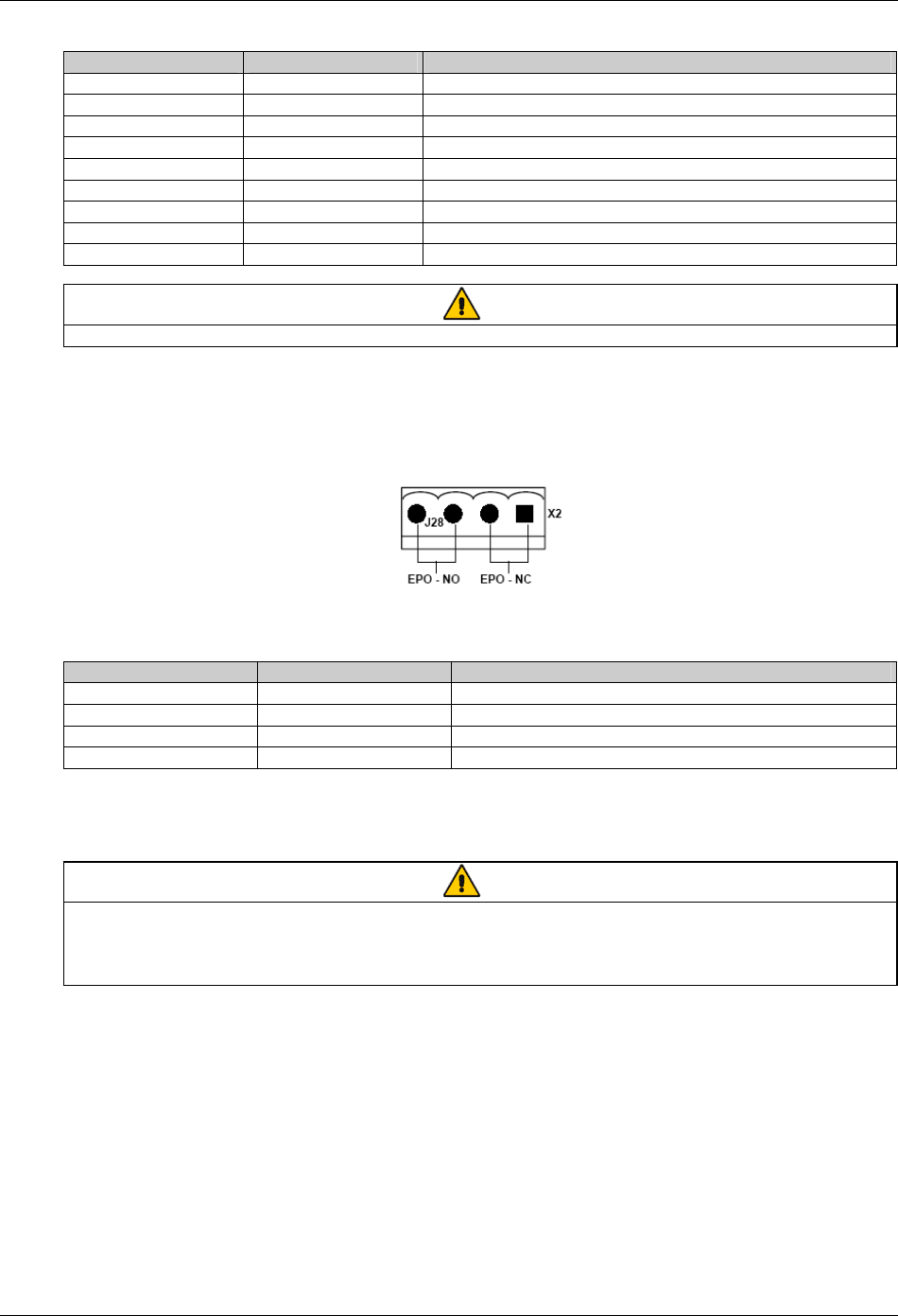
Figure 3-7 EPO input port
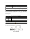
Table 3-6 Description of EPO input port
Position Name Description
J28.1 EPO_NC EPO activated when opened to J28.2
J28.2 EPO_NC EPO activated when opened to J28.1
J28.3 EPO_NO EPO activated when shorted to J28.4
J28.4 EPO_NO EPO activated when shorted to J28.3
The remote EPO facility is connected to the normally open or normally closed remote stop switch between these two
terminals using shielded cable. If this function is not used, terminals J28: 3&4 must be opened and J28: 1&2 must be
closed.
Note
The emergency stop action within the UPS shuts down the rectifier, inverter and static bypass. It does not internally disconnect the
input power supply. To disconnect ALL power to the UPS, open the upstream feeder breaker(s) when the remote EPO is
activated.
Normally closed EPO–J28: 1, 2, these terminals are supplied factory-linked on the monitor board.
Auxiliary DC power output port (X5)
The auxiliary DC power output port X5 provides auxiliary DC power for optional SNMP card. The voltage is between
9V to 12V. The maximum current is 500mA.
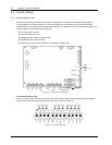
Communication ports
The communication ports include the serial ports RS232-1 and RS232-2, Intellislot intelligent communication ports.
1. Serial ports RS232-1 and RS232-2
RS232-1 provides serial data and is intended for direct use with Emerson UPSitePlus
TM
UPS monitoring software.
RS232-2 provides serial data and is intended for use by authorized commissioning and service personnel.