


Chapter 4 Operator Control And Display Panel 37
HIPULSE U UPS Single Module And “1+N” (Expandable) 160/200/300/400kVA User Manual
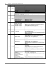
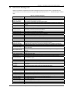
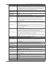
Alarm message Description
Inverter overtemp.
The temperature of the inverter heat sink is too high to keep inverter running. This alarm is triggered
by the signal from a temperature monitoring thermostat on the inverter bridge heat sink. The UPS will
recover automatically after a 5 minute delay from the disappearance of the overtemperature signal. If
the overtemperature condition is true, then check for and verify: 1. high ambient air temperature. 2.
blocked cooling airway. 3. any fan failure. 4. prolonged inverter overload
Fan fault At least one of the cooling fans has failed
Inverter STS fail
At least one of the static switches of inverter side is open or short circuit. This fault is locked until
power off
Bypass STS fail
At least one of the static switches of bypass side is open or short circuit. This fault is locked until
power off
Operation invalid This record is registered following an incorrect operation
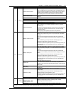
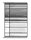
Unit over load
The UPS is confirmed to be overload when the load arises above 105% nominal rating. The alarm
automatically resets once the overload condition is removed. 1. Confirm that the alarm is true by
checking the load percent indicated on the LCD to determine which phase is being overloaded. 2. If
the alarm is true, measure the actual output current to verify that the indications are valid.
Disconnect unnecessary load and ensure the safety. In a parallel system, a severe load sharing error
can also leads to the alarm
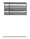
System over load
The UPS parallel system is confirmed to overload when the total load arises above 105% nominal
rating for the set basic number of UPSs. The alarm automatically resets once the overload condition
is removed.
1. Confirm that the alarm is true by checking the system load percent indicated on the LCD to
determine which phase is being overloaded. 2. If the alarm is true, measure the actual output current
to verify that the indications are valid.
Disconnect unnecessary load and ensure the safety. In a parallel system, a severe load sharing error
can also leads to the alarm
Unit over load timeout
The UPS is confirmed to overload and the overload times out.
Note 1: the highest loaded phase will indicate overload timing-out first. Note 2: When the timer is
active then alarm “unit overload” should also be active as the load is above nominal.
Note 3: When the timer has expired, the inverter Static Switch is opened and the load transferred to
bypass. The inverter shutdown and will restart after 10 seconds. Note 4: If the load decreases lower
than 95% after 5 minutes, the system will transfer back to inverter mode.
Confirm that the alarm is genuine by checking the load percent indicated on the LCD. If an overload
is indicated then check the load, and investigate any additional load connected prior to the alarm (if
applicable)
Byp. abnormal shutdown Both bypass and inverter voltages unavailable. Load interruption
Inverter over current Inverter pulse width modulation module overloaded
Bypass phase reverse
The phase sequence direction of bypass voltage is reversed. Normally, the phase of phase B lags
120 degrees behind phase A, and the phase of phase C lags 120 degrees behind phase B.
Verify that the phase rotation of the bypass supply presented to the UPS is correct, and rectify it if it
is found to be in error
Load impact transfer
A transfer to bypass occurred due to a large step load. The UPS should recover automatically. Turn
on connected equipment in sequential order to reduce the step loading of the inverter
Transfer time-out
The load is on bypass power due to excessive number of transfers that occurred within the last hour.
The UPS will recover automatically and will transfer the load back to inverter power within an hour
Load sharing fault UPS modules within a parallel system are not sharing the load current equally
DC bus abnormal DC input voltage to inverter beyond limits. Inverter shuts down. Load transfers to bypass
System transfer
The whole paralleled UPS system transferred to bypass at the same time. This message will appear
on the UPS which passive transfer to bypass
Parallel board fault
Malfunction of the paralleling control circuits of this UPS module. Can cause system transfer to
bypass
Parallel connect fault
The parallel cables are not connected correctly in a parallel system.
Reset the fault by pressing the FAULT CLEAR button, then restart the inverter by pressing the
INVERTER ON button
Bypass over current Bypass current is over limit above 135% rating. The UPS just alarms and does nothing
LBS Active
Load Bus Synchronization is active. The UPS is acting as an LBS master or slave in a dual bus
configuration
LBS abnormal
UPS set to LBS mode (master or slave), but no LBS signal on LBS bus. Check the LBS bus
connection
Byp. induct overtemp. Bypass load sharing inductor overtemperature. Check the environment and ventilation
Static Sw. overtemp. Overtemperature of static switch on bypass or inverter side. Check the environment and ventilation