


46 Chapter 6 Battery
HIPULSE U UPS Single Module And “1+N” (Expandable) 160/200/300/400kVA User Manual
Chapter 6 Battery
This chapter introduces the battery, including the battery safety points, installation, maintenance, and the battery
protection function, as well as the connections of the optional battery circuit breaker (BCB) box and battery
temperature sensor.
6.1 Introduction
The UPS battery consists of battery blocks connected in series to provide a nominal DC input voltage for the UPS
inverter. The required autonomy time (the time that the battery can maintain supply to the load in the event of a mains
failure) is limited by the ampere-hour size of the individual battery blocks and in some cases this could mean several
strings are connected in parallel.
It must be possible to disconnect the battery from the UPS module when undertaking maintenance or service
procedures. This is facilitated by means of a suitably rated circuit breaker which must be located as close as possible
to the battery terminals, and the power and control cables connected to the UPS using the most direct route possible.
If multiple sets of batteries connected in parallel are used to increase battery autonomy, the extension must be fitted
with a sectioning device to permit work to be performed on one set of batteries while the others remain in service.
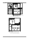
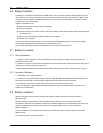
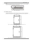
For external battery assembly, Emerson offers an optional battery circuit breaker (BCB) box, the features of which
depend on the size of the UPS. Normally, you must select a corresponding BCB box for each UPS, in order to
disconnect the battery from the UPS when the UPS requires maintenance or repair. The BCB box includes a BCB
control board. This box is designed to be either wall-mounted or assembled on a frame, and is connected between
the UPS and the battery. Refer to 6.9 BCB Box (Optional) for more information.
6.2 Safety
Special care should be taken when working with the batteries associated with the HIPULSE U UPS. When all the
cells are connected together, the battery terminal voltage will exceed 400V and is potentially lethal. A primary safety
consideration is to physically isolate the battery installation from all but appropriately qualified maintenance personnel;
which is best achieved by locating the cells in a key-lockable cabinet or a purpose-designed, dedicated battery room.
Warning
The following general battery safety precautions and warnings should be observed at all times:
1. A battery can present risk of electric shock or burn from high short circuit currents.
2. When connected in a string the voltage could be 460Vdc, this voltage is potentially lethal always observe high voltage
precautions.
3. Only qualified personnel should install or service batteries.
4. Eye protection should be work to prevent injury from accidental electrical arcs.
5. Remove rings, watches, necklaces, bracelets and all metal objects.
6. Only use tools with insulated handles.
7. Wear rubbers gloves and a rubber apron when handling batteries.
8. If a battery leaks electrolyte, or is otherwise physically damaged, it should be placed in a container resistant to sulphuric acid
and disposed of in accordance with local regulations.
9. If electrolyte comes into contact with the skin the affected area should be washed with plenty of clean water immediately.
10. Batteries must always be disposed of according to local environmental laws.
6.3 UPS Batteries
It is common practice in UPS installations to use valve-regulated cells. The term ‘valve regulated’ is used currently in
place of either ‘sealed’ or ‘maintenance free’ both of which have been used in the past.
Valve-regulated cells are not ‘sealed,’ and will vent, particularly on overcharge. The amount of gas given off is less
than for a flooded cell but when considering the design of the battery installation allowances must be made for