


Electrical Connections
15
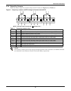
Frequency Converter Mode
If a frequency converter configuration is used, connect the AC input supply cables to the rectifier
input busbars (A-B-C terminals). Torque to 88 lb-in (10N-m) for M8 bolts. Ensure correct phase rota-
tion. There will not be any AC bypass supply cables to the bypass input (A-B-C terminals) and tighten
the connections.
2.2 Control Cables
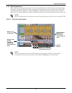
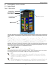
2.2.1 Monitor Board Features
Based on your site’s specific needs, the UPS may require auxiliary connections to manage the battery
system (external battery circuit breaker, battery temperature sensor), communicate with a personal
computer or provide alarm signaling to external devices or for Remote Emergency Power Off (REPO).
The monitor board, arranged for this purpose, is located on the rear of the operator access door. The
main features are:
• Input and Output dry contacts signal (one pair of contacts of relay)
• Emergency Power Off control (EPO)
• Environmental parameter input interface
• User communication (for data setting and user background monitor)
• Liebert IntelliSlot
®
interface
• Modem interface
• Temperature detect interface
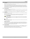
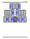
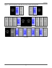
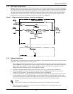
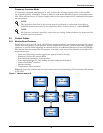
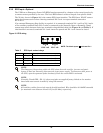
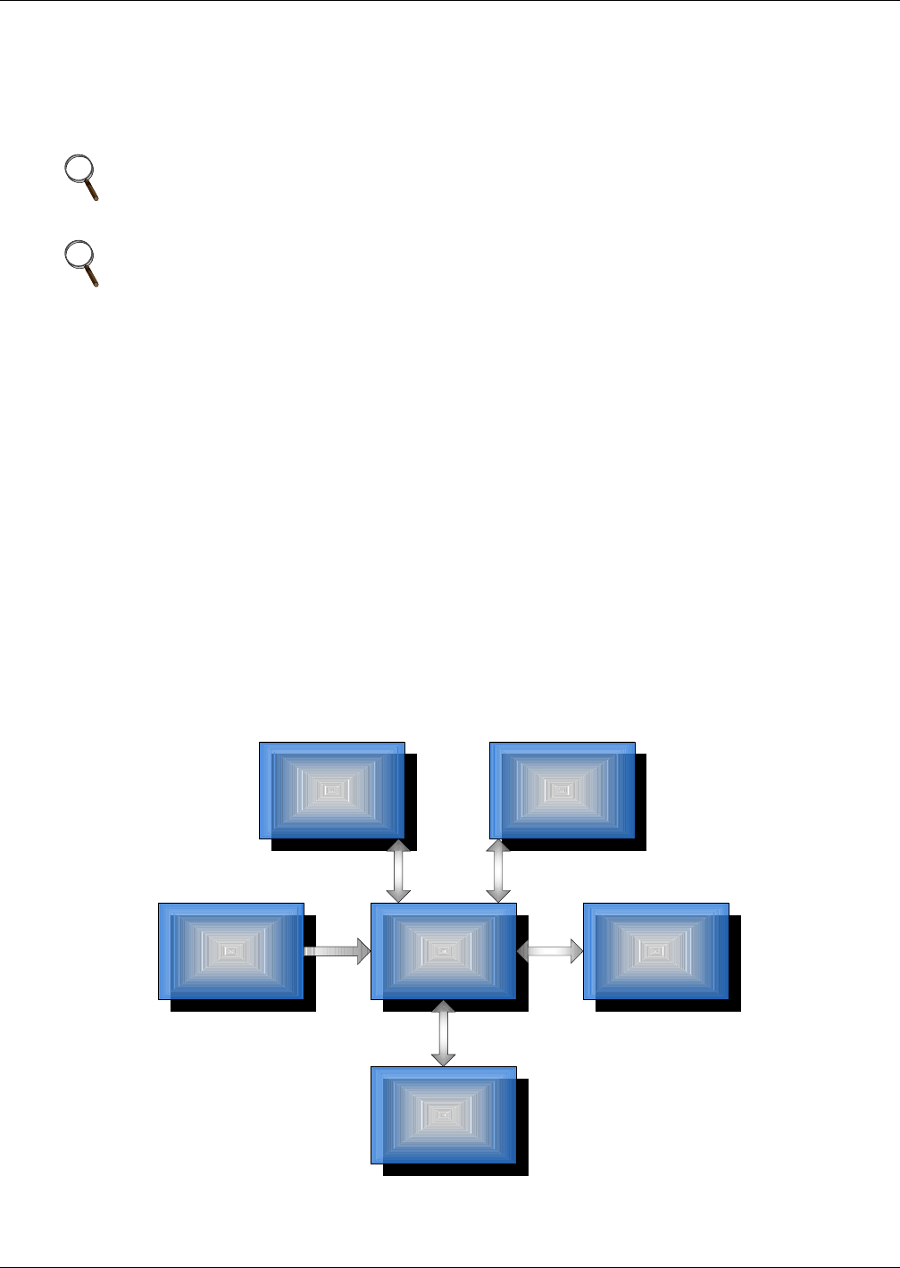
Figure 5 shows the relationship and connection between the monitoring (U2) board and other boards
in the UPS.
Figure 5 Monitor board U2
NOTE
The operations described in this section must be performed by authorized electricians or
qualified technical personnel. If any difficulties arise, contact Liebert at 1-800-LIEBERT.
NOTE
For frequency converter operation, ensure that the linking busbars between the bypass and the
rectifier input are removed.
X1
User Interface
Board
U1
DSP Control
K1
Key & LED Board
U2
Monitor Board
M3
Parallel Logic
Board
M5
Auxiliary Power