


Electrical Connections
20
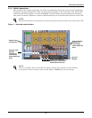
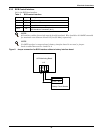
2.3.5 EPO Input—Optional
The UPS has an Emergency Power Off (EPO) function operated by a button on the control panel or by
a remote contact provided by the user. The local EPO button is under a hinged, clear plastic shield.
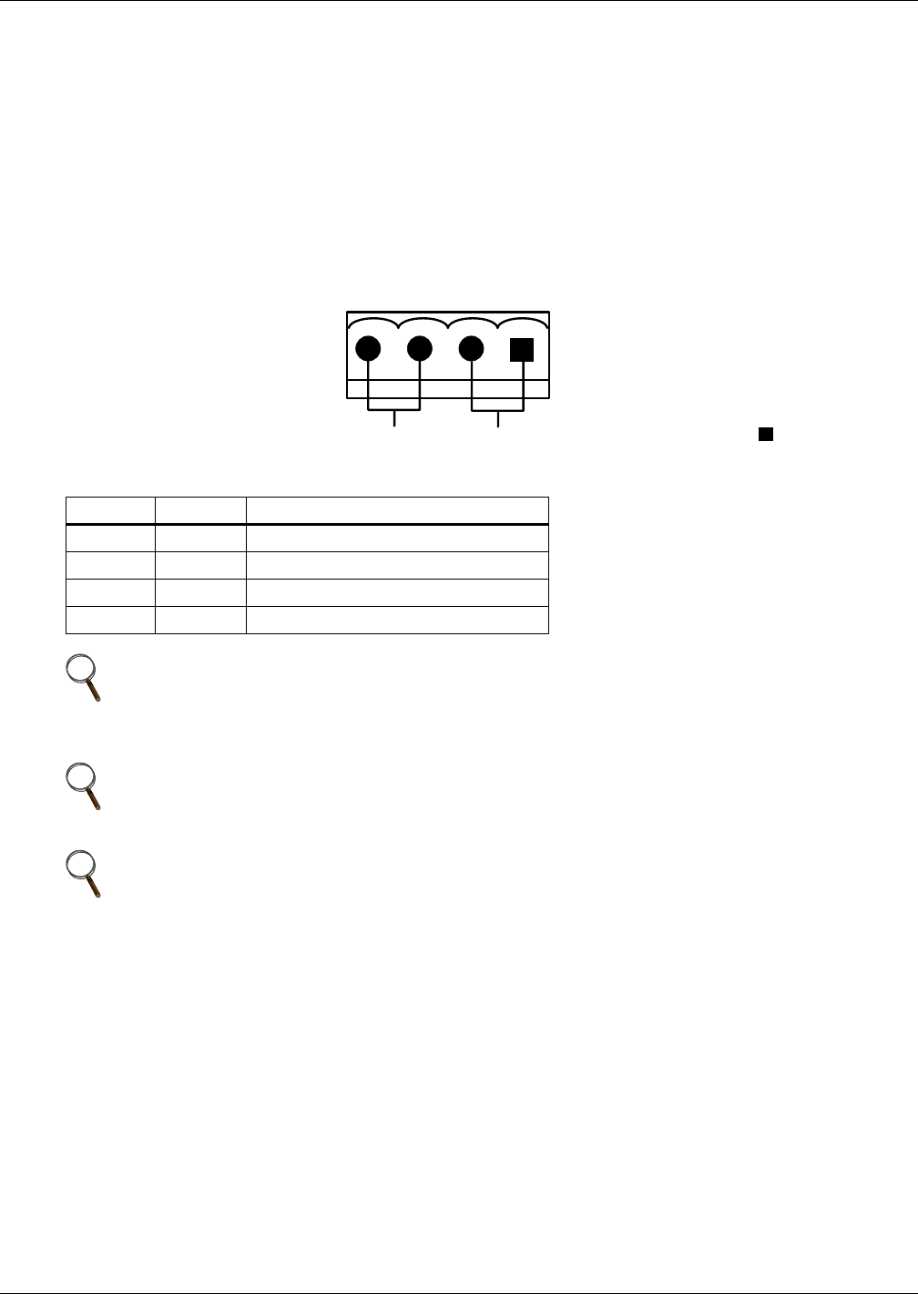
The X2 slot, shown in Figure 10, is the remote EPO input interface. The EPO has a NO/NC contact
point that becomes active when shorting terminals X2: 3 and 4 or open terminal connection
X2: 2 and 1.
If an external Emergency Stop facility is required, it is connected terminals X2: 1 and 2 or X2: 3 and 4
of the auxiliary terminal block (X2). It also is connected to the Normally Open or Normally Closed
remote stop switch between these two terminals using shielded cable (see Figure 10 and Table 5). If
this function is not used, terminals X2: 3 and 4 must be opened and X2: 1 and 2 must be closed.
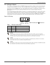
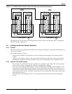
Figure 10 EPO wiring
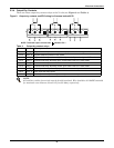
Table 5 EPO input contact relays
Position Name Description
J28.1 EPO_NC EPO Activated when opened to J28.2
J28.2 EPO_NC EPO Activated when opened to J28.1
J28.3 EPO_NO EPO Activated when shorted to J28.4
J28.4 EPO_NO EPO Activated when shorted to J28.3
NOTE
The Emergency Stop action within the UPS shuts down the rectifier, inverter and static
bypass. It does not internally disconnect the input power supply. To disconnect ALL power to
the UPS, open the upstream feeder breaker(s) when the remote EPO is activated.
NOTE
Normally Closed EPO – X2: 1,2, these terminals are supplied factory-linked on the monitor
board and must remain installed if using NO contacts.
NOTE
All auxiliary cables of terminal must be double-insulated. Wire should be 20-16AWG stranded
for maximum runs between 82 and 197 feet (25-60m), respectively.
EPO - NO
EPO - NC
J28
X2
NOTE: The black square indicates Pin 1.