


Electrical Connections
19
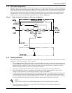
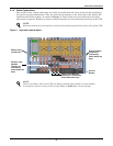
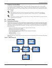
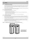
2.3.4 Output Dry Contacts
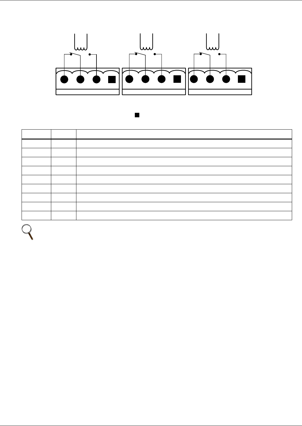
There are three output dry contact relays at the X1 slot (see Figure 9 and Table 4).
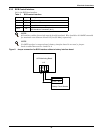
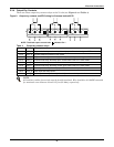
Figure 9 Output dry contacts and EPO wiring for firmware before M170
Table 4 Output dry contact relays
Position Name Description
J13.2 BFP_O Bypass feedback protection relay. Normally open. Closed when bypass SCR is shorted.
J13.3 BFP_S Bypass feedback protection relay center
J13.4 BFP_C Bypass feedback protection relay. Normally closed. Open when bypass SCR is shorted.
J21.2 INV_O Inverter mode relay. Normally open. Closed when UPS is in inverter mode.
J21.3 INV_S Inverter mode relay center
J21.4 INV_C Inverter mode relay. Normally closed. Open when UPS is in inverter mode.
J25.2 ACF_O Main input fault relay. Normally open. Closed when main input is in fault.
J25.3 ACF_S Main input fault relay center
J25.4 ACF_C Main input fault relay. Normally closed. Open when main input is in fault.
NOTE
All auxiliary cables of terminal must be double-insulated. Wire should be 20-16AWG stranded
for maximum runs between 82 and 197 feet (25-60m), respectively.
J25
ACF_O
ACF_S
ACF_C
J21
INV_C
INV_S
INV_O
X1
J13
BFP_C
BFP_S
BFP_O
NOTE: The black square on each slot indicates Pin 1.