Installation Drawings
43
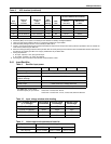
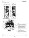
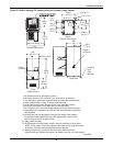
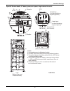
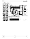
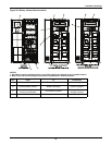
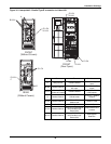
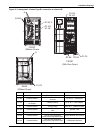
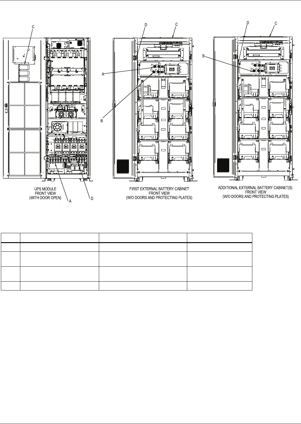
Figure 28 Battery cabinet interconnection
NOTES:
1. All cables must be repositioned prior to and while setting the cabinets in their installed location.
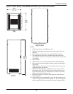
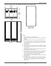
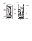
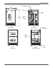
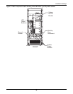
2. Refer to the individual drawing of each piece of equipment for additional details.
Run From To Conductors
A UPS Battery Terminal Block First External Battery Cabinet Positive, Negative
B External Battery Cabinet
Additional External
Battery Cabinet(s)
Positive, Negative
C
Battery Cabinet(s) Breaker
Control Terminal Block
UPS Monitoring Board
Battery Breaker
Auxiliary Contacts
D UPS Ground Battery Cabinets Ground Ground


