


Installation Drawings
45
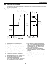
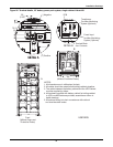
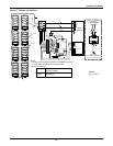
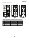
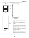
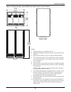
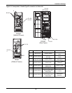
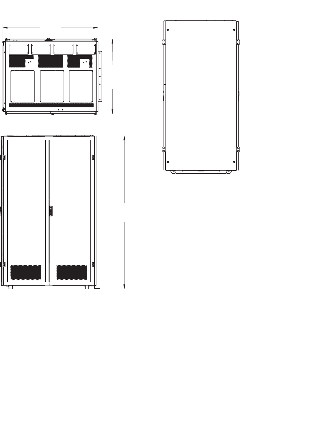
Figure 30 Outline drawing, Liebert NX480V, 80-120kVA Type E1 parallel cabinet
1240
(48.8)
965
(38)
2000
(78.7)
To p
Right Side
Front
NOTE:
1. All dimensions are in millimeters (in).
2. Eight-inch minimum clearance above unit required for air
exhaust.
3. Keep cabinet within 15 deg. of vertical while handling.
4. Top and bottom cable entry available through removable
access plates. Remove access plate punch to suit conduit
size and replace.
5. Color - black.
6. Unit bottom is structurally adequate for forklift handling.
7. M10 threaded mounting holes used for seismic anchoring
or floor stand.
NOTE: If floor stand is used, the weight of the unit must
be supported under all casters.
8. Each mounting location is supported by two 10 ga. (.135")
galvanized steel. The threaded insert is approximately
3/4" deep. Mounting holes are underneath unit base;
mounting bolts must be threaded into unit.
9. Side panels must be removed from adjacent units that are
bolted together.
10. Leveling feet are not designed to carry the full weight of
the cabinet. Finger-tighten leveler against the floor, then
tighten with a wrench less than 2 turns for friction fit
against floor.