58
MODEL 5081-T SECTION 8.0
FOUNDATION FIELDBUS OPERATION
SECTION 8.0
FOUNDATION FIELDBUS OPERATION
This section covers basic transmitter operation and software functionality. For detailed descriptions of the function blocks
common to all Fieldbus devices, refer to Fisher-Rosemount Fieldbus FOUNDATION Function Blocks manual, publication
number 00809-001-4783.
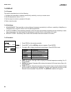
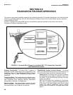
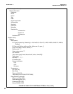
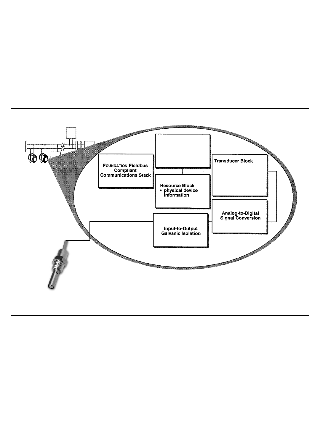
Figure 8-1 illustrates how the pH/ORP signal is channelled through the transmitter to the control room and the
FOUNDATION
Fieldbus configuration device.
FIGURE 8-1. Functional Block Diagram for the Model 5081-T-FF Conductivity Transmitter
with FOUNDATION Fieldbus.
SENSOR
Function Blocks
• AI1
• AI2
• Al3
• PID
• sensor type
• engineering units
• reranging
• damping
• temperature compensation
• calibration
• diagnostics
Software Functionality. The Model 5081-T software is
designed to permit remote testing and configuration of the
transmitter using the Fisher-Rosemount DeltaV Fieldbus
Configuration Tool, or other FOUNDATION fieldbus com-
pliant host.
Transducer Block. The transducer block contains the actu-
al measurement data. It includes information about sensor
type, engineering units, reranging, damping, temperature
compensation, calibration, and diagnostics.
Resource Block. The resource Block contains physical
device information, including available memory, manufac-
turer identification, type of device, and features.
FOUNDATION fieldbus Function Blocks. The Model
5081-T includes three Analog Input (AI) function blocks and
one PID function block as part of its standard offering.
Analog Input. The Analog Input (AI) block processes
the measurement and makes it available to other func-
tion blocks. It also allows filtering, alarming, and engi-
neering unit change.
PID. The PID function block combines all of the neces-
sary logic to perform proportional/integral/derivative
(PID) control. The block supports mode control, signal
scaling and limiting, feedforward control, override
tracking, alarm limit detection, and signal status propa-
gation.


