81
MODEL 5081-T SECTION 10.0
DIAGNOSIS AND TROUBLESHOOTING
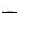
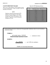
10.6 RTD RESISTANCE VALUES
Table 10-4 is a ready reference of RTD resistance values
at various temperatures. These are used for test and
evaluation of the sensor.
NOTE
Resistance values are read across the RTD
element and are based on the manu-
facturer’s stated values (±1%). Allow
enough time for the RTD element in the
sensor to stabilize to the surrounding
temperature (10 min).
Temperature Pt-100 Pt-1000
(
°
C) Resistance (ohms) Resistance (ohms)
0 100.00 1000
10 103.90 1039
20 107.79 1078
25 109.62 1096
30 111.67 1117
40 115.54 1155
50 119.40 1194
60 123.24 1232
70 127.07 1271
80 130.89 1309
90 134.70 1347
100 138.50 1385
Table 10-4. RTD Resistance Values.
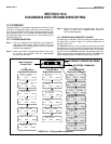
FIGURE 10-5. Conductivity Determination
FORMULA:
EXAMPLE:
cell constant value x 1,000,000
desired simulated conductivity in µs/cm
.01 x 1,000,000
10 µs/cm
Use the following formula to determine the appropriate resistance value to use to simulate a
conductivity value:
= resistance in ohms
= use 1,000 ohm resistance


