79
MODEL 5081-T SECTION 10.0
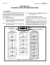
DIAGNOSIS AND TROUBLESHOOTING
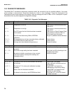
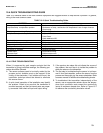
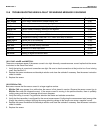
SYMPTOM ACTION
Wrong temperature reading. Perform a temperature standardization. Verify sensor's RTD.
Suspected temp. compensation problem. Resistance vs. temp.; see Section 8.6 Temperature is out of range of sensor.
Check wiring.
Display segments missing. Display inoperable. Replace Display board.
Analyzer locks up; won't respond. Replace PCB stack
Press Reset.
Check batteries in IRC.
Erratic displays. Check sensors in process.
Transmitter won't respond to IRC key presses. Verify and clean ribbon cable connection on CPU board. Check batteries in IRC.
Key press gives wrong selection. Replace IRC. Check ribbon cable connection on CPU board.
Wrong or no current output. Verify that output is not being overloaded; remove load; replace PCB stack.
No display or indicators. Replace PCB stack.
”Excess Input” Check sensor wiring.
“Reverse Input” Perform sensor zero.
“Check sensor zero” Analyzer will not zero. Place sensor in air and access zero routine.
Table 10-3 identifies some of the more common symptoms and suggests actions to help resolve a problem. In general,
wiring is the most common cause.
10.4 QUICK TROUBLESHOOTING GUIDE
TABLE 10-3. Quick Troubleshooting Guide.
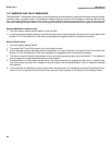
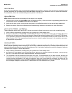
When it is apparent by grab sample analysis that the
transmitter is giving inaccurate readings, the following pro-
cedure should be followed.
A. The sensor surfaces need to be totally wetted by the
process and air bubbles must no be trapped in the
vicinity of the electrodes. If air bubbles are found, the
installation technique should be altered to eliminate
this source of error.
B. A quick visual inspection of the installation may identify
the problem. Check to be sure that the transmitter is
mounted securely and that its internal parts are proper-
ly connected. Next check all input and output wiring.
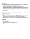
C. If the previous two steps did not indicate the source of
the problem, the next step is to isolate the problem to
either the sensor or the transmitter.
D. The first step in troubleshooting the sensor is to discon-
nect it from the transmitter, remove the sensor from the
process and thoroughly dry the sensor electrodes. Refer
to sensor manual for additional troubleshooting checks.
E. To troubleshoot the transmitter independently of the
sensor, use an appropriate resistor across the temper-
ature input connectors and connect the conductivity
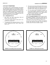
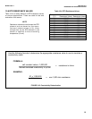
inputs to resistance decade box. Refer to Figure 10-7
to reference the conductivity simulation values.
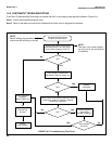
10.4.1 FIELD TROUBLESHOOTING


