MODEL 5081-T SECTION 10.0
DIAGNOSIS AND TROUBLESHOOTING
10.2 FAULT CONDITIONS
Three classes of error conditions/problems are detected
and differentiated between by the diagnostic program.
System disabling problems are faults caused by failures
in the loop or significant variations in the process.
System non-disabling problems are warnings and deal
with input or A to D conversion settings. The third class
of detected problems are error messages and occur
when the calibration limits are exceeded.
10.2.1 DISABLING FAULTS
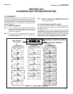
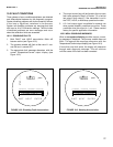
1. Both FAULT and HOLD annunciation fields will
become active (see Figure 10-3).
2. The process variable will flash at the rate of 1 sec-
ond ON and 1 second OFF.
3. The appropriate fault message alternates with the
normal Temperature/Current output display (see
Figure 10-2).
CALIBRATE PROGRAM DIAGNOSE
“ [5P1!2-5[” !!!
EXIT NEXT ENTER
'"""
µS/cm
F
A
U
L
T
H
O
L
D
♥
FIGURE 10-2. Disabling Fault Annunciation
CALIBRATE PROGRAM DIAGNOSE
“ 5P:VU!@M-SP” !
EXIT NEXT ENTER
'"""
µS/cm
♥
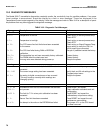
FIGURE 10-3. Warning Annunciation
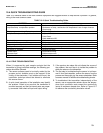
4. The output current loop will be forced to the non-zero
fault value entered in Step 3 of Section 7.2 or held at
last value if fault value=0, if the transmitter is not in
the TEST, HOLD, or Multidrop operational modes.
5. A 0-1 mA output signal is available for external use
when system disability conditions are active. These
conditions drive this output to 1 mA. Please contact
factory for specific application information.
10.2.2 NON- DISABLING WARNINGS
When a non-system-disabling condition occurs, a warn-
ing message is displayed. The process variable does not
flash. The appropriate message alternates with the
Temperature/Current output display (see Figure 10-3).
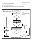
If more than one fault exists, the display will sequence
through each diagnostic message. This will continue
until the cause of the fault has been corrected.
77


