


Instruction Manual
IM-105-4000, Original Issue
August 2005
2-3
OPM 4000
Alignment of Stack
Flanges
Stack flange alignment is described in Installation of Stack Flanges and is the
first step in successful installation. The final beam alignment adjustments are
described in the Beam Alignment Procedure.
Installation of Stack
Flanges
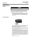
For an opacity monitor, the customer is required to supply and install two 3 in.
IPS flanges at eye level directly across from each other. The flange faces,
mounted on pipe stubs, should be approximately 6 to 8 in. (152 to 203 mm)
from the stack or insulation. On completion of the installation, the flanges
must be aligned so that the total deviation of the light source flange relative to
a common centerline does not exceed ±1
o
and the retro reflector flange does
not exceed ±3
o
.
Flanges should be mounted approximately 5 feet (1,5 m) up from the deck of
the platforms, roof or walk way.
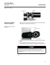
At installations where conditions permit, this may be accomplished by using a
piece of 2-1/2 in. (63,5 mm) pipe suspended across the stack protruding far
enough to allow slipping the 3 in. flange pipe assemblies over each end and
welding in place as shown in Mounting: Under 6 ft (1,8 m) Diameter drawing
in Section 8.
Any deviation up to the previously specified limits can be adjusted during the
installation and alignment of the light source and retro reflector with the
system's alignment adjustments.
Where installations do not permit the use of the method mentioned above, the
following procedure will accomplish the same results. (See Mounting: Over 6
ft (1,8 m) Diameter drawing in Section 8). An alignment tool can be purchased
from the factory to ensure accurate alignment.
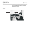
Accurately locate one 3-1/2 in. (89 mm) diameter hole (large enough to
accept the 3 in. pipe) and the other hole approximately 1/2 in. (12,7 mm)
diameter, directly across from each other. Attach the alignment tool to the
flange/pipe assembly and insert the pipe into the 3-1/2 in. (89 mm) hole in the
stack wall. Align the assembly with the 1/2 in. (12,7 mm) diameter hole on the
opposite side by viewing through the alignment tool and weld the pipe in
place. Care must be exercised when welding to maintain alignment.
The 1/2 in. (12,7 mm) diameter hole should now be enlarged approximately
3-1/2 in. (89 mm) to accept the other flange/pipe assembly. Proceed in the
same manner, installing the assembly with the alignment tool attached, and
weld in place maintaining concentric alignment with the 3 in. pipe previously
installed on the opposite wall.
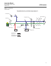
Sample Area
To achieve a representative sample, the accepted practice is to have the
measurement path of the instrument directly in the center of the stack. An
area should be chosen where the gases are not stratified in the stack or duct.
When installed near a bend, install the transceiver in the plane defined by the
bend. Avoid locations where large amounts of condensed water may be
present.