


Instruction Manual
IM-105-4000, Original Issue
August 2005
4-1
OPM 4000
Section 4 Operation
OPM 4000 Operations and Adjustments . . . . . . . . . . . . . page 4-1
Service Module . . . . . . . . . . . . . . . . . . . . . . . . . . . . . . . . . . page 4-4
OPM 4000 OPERATIONS
AND ADJUSTMENTS
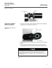
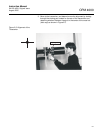
The OPM 4000 consists of transceiver, retro reflector, service module and the
control unit. The maintenance module has a digital display for reading opacity
from the control unit and T2 from the transceiver. It also has connections for
attaching a meter for troubleshooting or calibration when necessary. Other
switches are provided for initiating zero and span modes during service or
maintenance. If any switch causes the system to read other than stack
opacity, the Control unit Fault Alarm system will be energized notifying the
operator. A fault output signal (open transistor collector) is also energized for
use with other alarms or DAS system, which need to know opacity readings
are not representative of the actual stack opacity and a fault condition exists.
Only two conditions are considered normal operation; 1- Reading smoke,
2- Computer or internal clock initiated calibration check cycle.
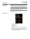
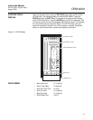
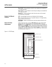
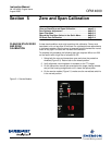
Front Panel LED's
ALARM - Red LED is blinking when a fault is detected. Manual Cal.
RUN - Green LED is on during normal operation and blinking if system is in
S/M mode. The primary reason for S/M mode is to prevent 4-20 mA outputs
from changing when user is modifying blockware.
OPERATE - Red LED is on during normal operation.
AUTO/MAN - Red LED is on during calibration check mode.
ZERO - Red LED is on when zero cal cycle is in progress, out during span or
normal operation.
SPAN - Red LED is on when span cal cycle is in progress, out during zero or
normal operation.
HIGH OPACITY - Red LED is on if opacity exceeds set point for more than
the time delay (typically 30 seconds).
REM/LOC - Red LED always out (this is not used).
Fault Messages
Air purge low - Airflow to the transceiver and/or retro reflector is not
sufficient.
No Stack Power - Indicates loss of service module power loss or other
related power or component failure from the service module.
T2 4-20 Lost/low - Transceiver 4-20 mA current loop is out of specification or
missing.
Maintenance Mode - Indicates a maintenance mode switch on the service
module is in a position and the system is not displaying or outputting the
smoke reading.
Window Dust - Dirt has accumulated on the transceiver lens and/or the zero
mirror in excess of the > 5% limit and must be cleaned.