Instruction Manual
IM-105-4000, Original Issue
August 2005
OPM 4000
2-8
Air Flow Switch
If you have an airflow alarm when the system is powered, check the airflow
switch. With the blower running and the source under normal conditions,
disconnect the leads of the switch and place an ohmmeter across them. The
switch should be closed, less than 2 ohms, if flow is enough to over-come
stack pressure and blower inlet is clear. Cover the air cleaner inlet and verify
the switch opens. Replace the leads when the test is complete.
Control Unit
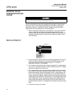
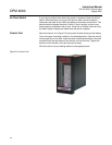
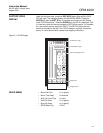
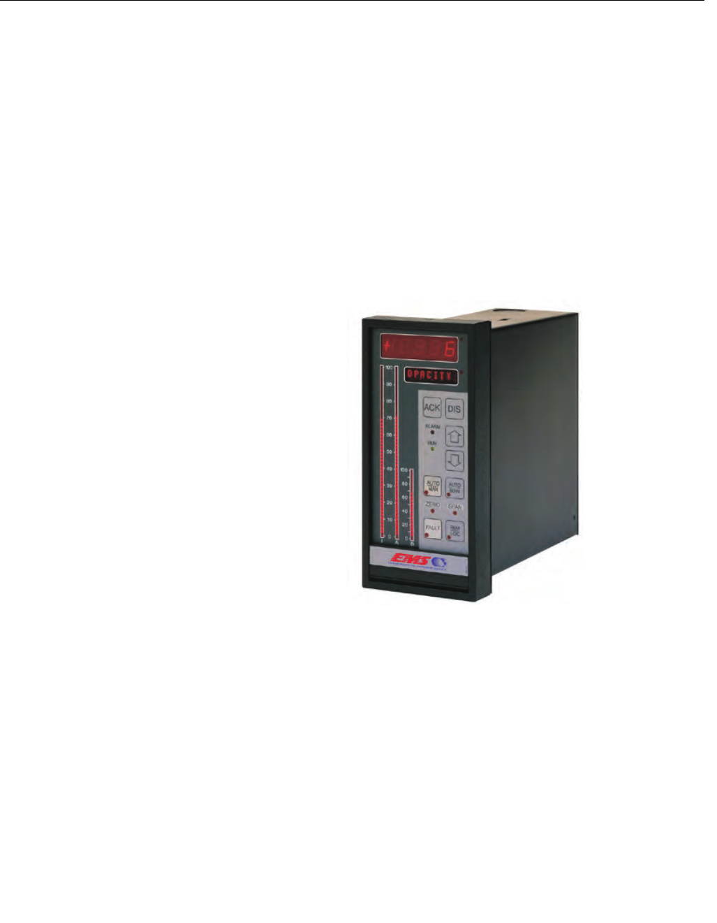
Mount the control unit (Figure 2-6) at eye level for best viewing of the display.
Cut out for panel mounting is shown in the drawing section. Insert the control
unit through the cut-out hole. Insert the panel mounting hardware in the slots
provided in the top and bottom of the control unit from the rear. Tighten the
screws until the control unit is securely held in place.
Wire the control unit per drawing section and energized power.
Figure 2-6. Control Unit


