


Instruction Manual
IM-105-4000, Original Issue
August 2005
OPM 4000
http://www.raihome.com
Section 5 Zero and Span Calibration
Clear on Stack Zero and Span Calibration . . . . . . . . . . . . page 5-1
Zero Reflector Adjustment . . . . . . . . . . . . . . . . . . . . . . . . . page 5-2
Span Filter Mark . . . . . . . . . . . . . . . . . . . . . . . . . . . . . . . . . page 5-3
Record the Zero/Span Values in the Quick Menu . . . . . . page 5-4
Off Stack Zero Calibration . . . . . . . . . . . . . . . . . . . . . . . . . page 5-4
CLEAR ON STACK ZERO
AND SPAN
CALIBRATION
A clear stack condition must exist to perform this calibration. Power must
have been on for no less than 30 minutes. Do not attempt these adjustments
in inclement weather. After the cover is removed from the transceiver normal
levels of day light in the area will not effect the calibration.
To complete this procedure the following items are required: Micro-turn 200
on-line test kit with a high filter of at least 0.8 OD.
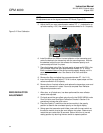
1. Swing both the retro and transceiver open and clean the protective
windows (Figure 5-3). Return both to the closed position.
2. Verify alignment; returning beam is centered on the TTL target.
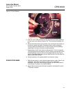
3. On the transceiver remove the screw below the target viewing window
and pull the housing straight back until it clears the optical plate.
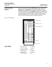
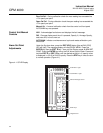
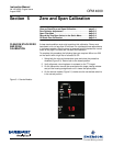
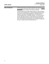
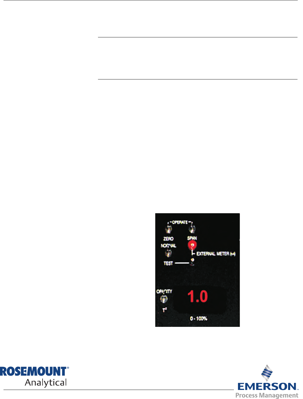
4. On the service module (Figure 5-1) make sure the normal/test switch is
in the normal position.
Figure 5-1. Service Module