


Instruction Manual
IM-105-4000, Original Issue
August 2005
OPM 4000
4-4
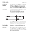
Remote Calibration
Cycle Initate
To have an external device cause the monitor to begin calibration cycle,
connect an N.O. dry contact to terminal 8L and 9. A momentary closure will
initiate a 3-minute zero and a 3-minute span check cycle. Total time of
calibration check is 6 minutes.
Remote Calibration
Cycle Acknowledgment
Cal in progress - By dry contacts on terminal 4U (common) and 5U (NC). This
contact remains closed until cal is completed, i.e. both zero and span.
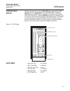
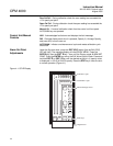
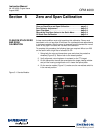
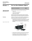
SERVICE MODULE
The service module is used to pass signals to and from the transceiver and
control unit, display opacity via digital meter, initiate maintenance zero and
span cycles and insertion of external current meter in the transceiver to
control unit 4-20 mA loop.
OPACITY / T2 - This switch selects the display of the stack digital meter. In
the opacity mode the digital displays % opacity from the control unit. In the T2
mode it is the signal out of the transceiver in % Transmittance
2
.
OPERATE / ZERO - This switch controls the zero mirror solenoid. In the
operate position the mirror is not
in the measuring path and is considered
normal
operation. When the mirror solenoid is energized, the mirror is placed
in
the measurement path and is considered a maintenance condition, i.e.
signal is not representative of the stack smoke. The control unit will indicate a
fault.
• Energize and observe the digital meter to test the systems response
to zero % opacity.
• Energize in conjunction with the span filter to observe the up scale
span % opacity calibration point.
OPERATE / SPAN - This switch controls the span filter solenoid. In the
operate position the span filter is not
in the measuring path and is considered
normal
operation. When the span filter solenoid is energized, the span filter is
placed in
the measurement path and is considered a maintenance condition,
i.e., signal is not representative of the stack smoke. The control unit will
indicate a Fault.
• Energize in conjunction with the zero mirror to observe the up scale
span calibration point.
NORMAL / TEST - This switch controls the EXTERNAL mA METER
connections. In the normal mode the terminals are shorted. In the test mode
the terminals are open and the current loop from the transceiver is interrupted
allowing the use of an external current meter to be placed in series with the
transceiver current output. When this is in the test mode position it is
considered a maintenance condition and fault condition. If no current meter is
in the test jacks, the loop current the control unit will indicate will be full scale
and the control unit will indicate a fault.