


Instruction Manual
IM-105-4000, Original Issue
August 2005
2-5
OPM 4000
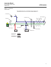
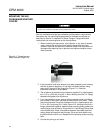
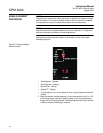
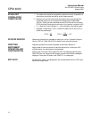
Figure 2-2. Air Plenum
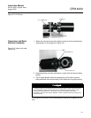
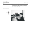
Transceiver and Retro
Reflector Assembly
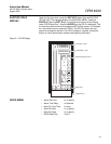
1. Attach the transceiver and retro reflector to the air plenum assembly by
placing them on the hinge pins (Figure 2-3).
Figure 2-3. Upper and Lower
Hinge Pins
2. Close transceiver and retro and secure in place with the two hold down
latches.
3. The air-purge blowers should be powered up at this time to prevent
stack particulate from accumulating in the nipple and air-purge housing.
All wiring from the control unit to the transceiver should be completed at this
time.
Air Plenum
3 in. 125# Flange
Middle Plate
Upper Hinge Pin
Lower Hinge Pin
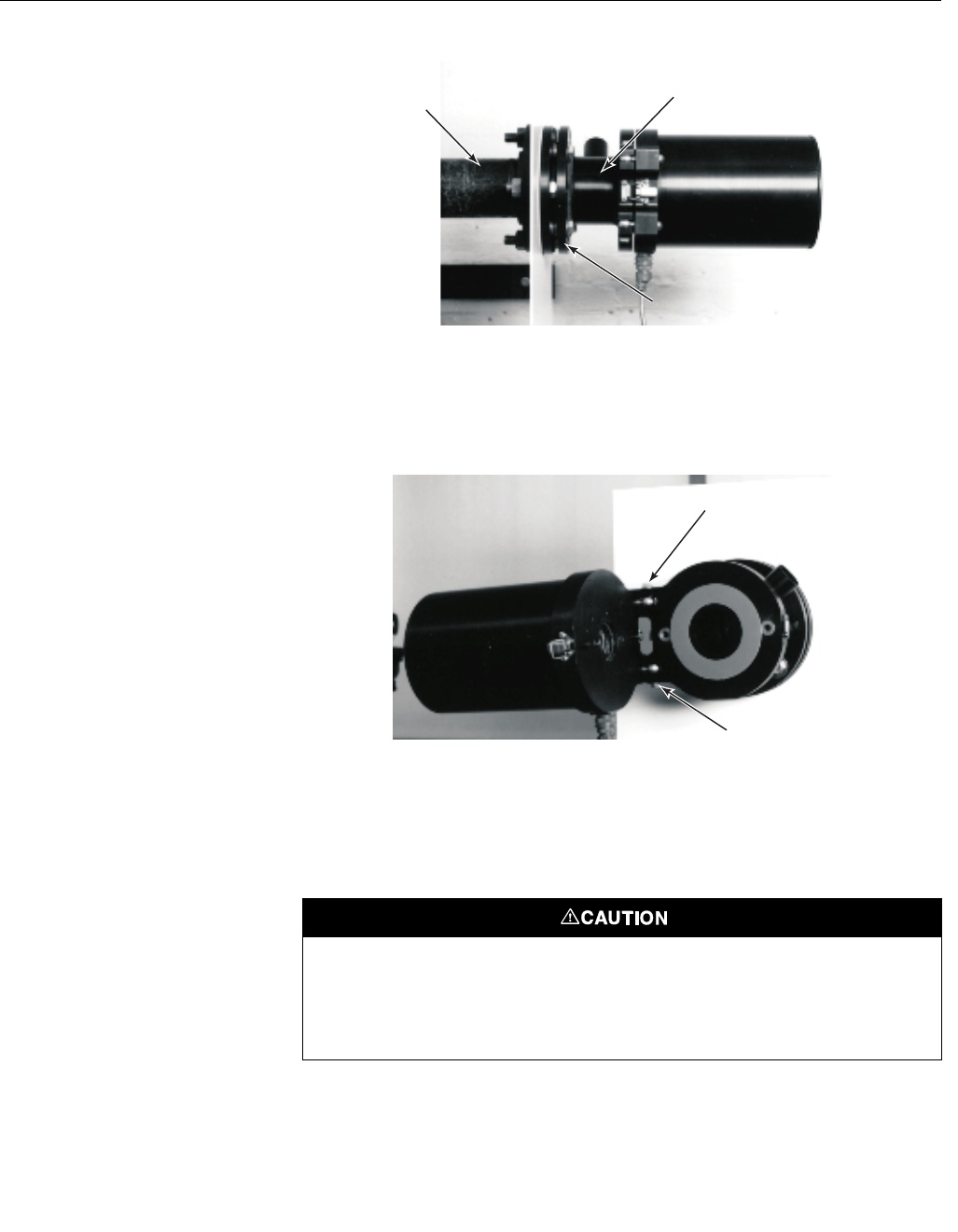
If installed location has a positive pressure the air-purge system must be used continuously
during installation to prevent process gases from contaminating optical surfaces or over
heating instrument electronics. If the system is shut off for more than momentary
interruptions, the instrument may be damaged. Failure to provide continuous air-purge may
void the warranty.