Instruction Manual
IM-105-4000, Original Issue
August 2005
OPM 4000
2-4
MOUNTING THE AIR
PLENUM AND WEATHER
COVERS
After the installation site has been selected and the platform requirements
have been met, the mounting flanges should be installed and aligned as
described in Section 2, Installation of Stack Flanges. Flanges should be
installed with the mounting faces on the vertical plane.
1. Before installing the transceiver, retro reflector, or any type of weather
cover, remove the air plenum from both the transceiver and retro
reflector. Removal will make the installation easier with less chance of
damage while attaching the air plenums and optional weather covers
when provided.
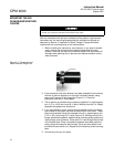
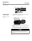
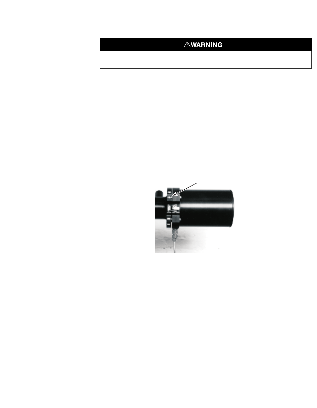
Figure 2-1. Transceiver and
Retro Reflector Hinge Pins
2. If the transceiver and retro reflector have been shipped from the factory
with the air plenum attached, un-clip both hold down latches, swing
open and lift up and off the hinge pins (Figure 2-1). Place the
transceiver and retro in a safe place.
3. The air plenum is attached to the customer supplied 3 in. pipe flange by
four 2-1/2 in. (63,5 mm) long 5/8-11 bolts. Working from the 3 in. flange,
assemble the gasket then air plenum.
4. If you have weather covers remove the two weather cover hood hinge
pins located on the upper right and left hand corner of the hood. The air
plenum and weather cover are attached to the 3 in. pipe flange by four
2-1/2 in. (63,5 mm) long 5/8-11 bolts (Figure 2-2). Working from the 3 in.
flange, assemble the gasket, weather cover mounting plate, gasket, and
mating flange, and air plenum. Place the 5/8-11 bolt through the top hole
of the middle plate. Place a flat washer between the middle plate and
mating flange and pass the bolt through. Slip a split lock washer over
the bolt and secure with a nut. Repeat for the remaining three mounting
bolts.
5. Connect any wiring or air hoses.
Control unit, Transceiver and Retro serial numbers must match.
Hinge Pin


