


Instruction Manual
IM-105-4000, Original Issue
August 2005
OPM 4000
2-6
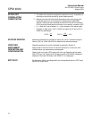
BEAM ALIGNMENT
PROCEDURE
NOTE
Alignment can not be done unless the power is applied to the stack mounted
service module. The control unit does not have to be connected or powered.
For alignment accuracy, the stack should be at normal temperature.
NOTE
Alignment should be completed before instrument calibration. For alignment
accuracy, the stack should be at normal temperature.
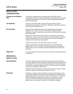
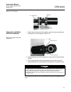
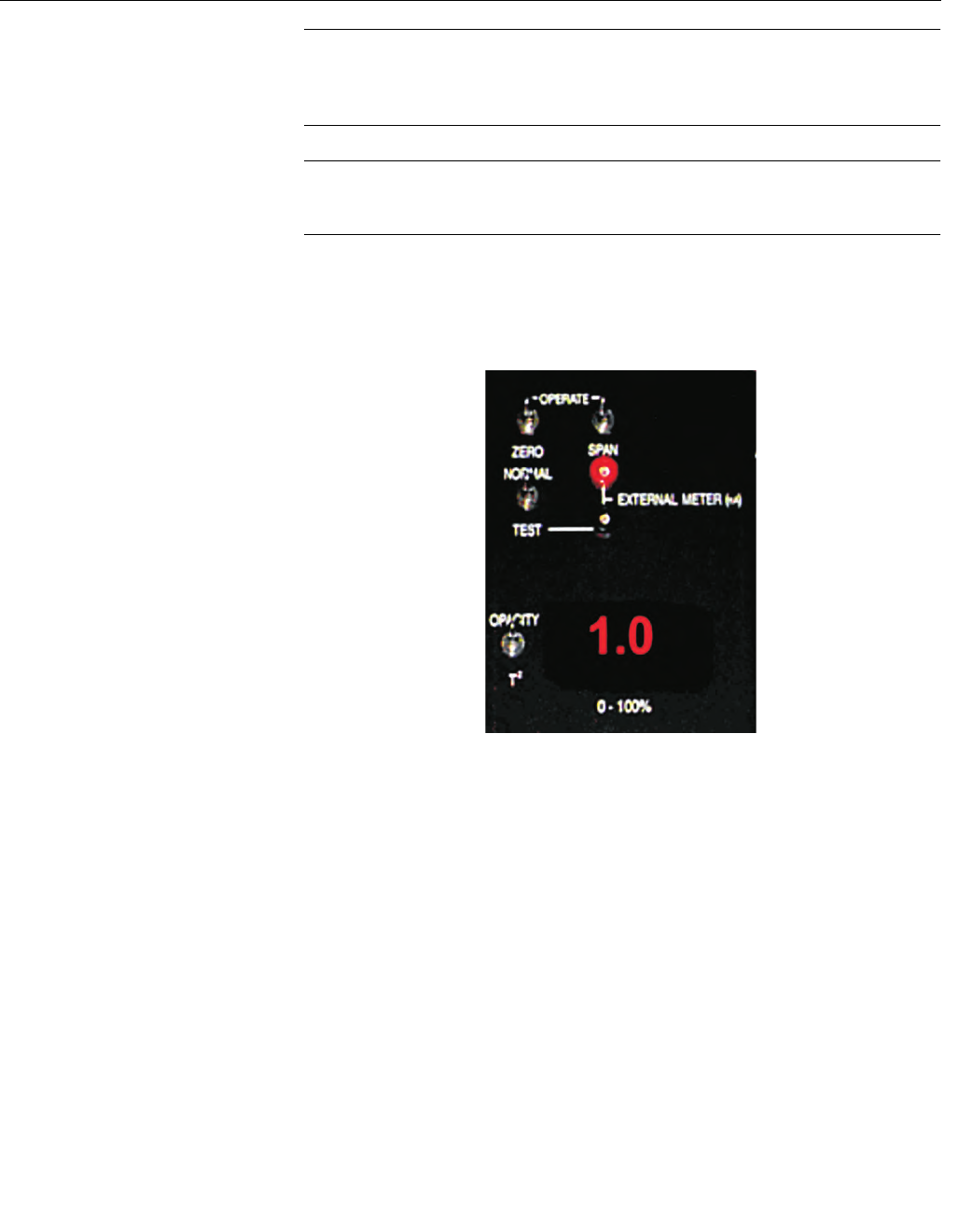
Maintenance module switches (Figure 2-4) should be in the normal type
operating positions.
Figure 2-4. Service Module
Switch Location
• Zero/Operate - Operate
• Span/Operate - Operate
• Normal/Test - Normal
• Opacity/T
2
- Opacity
1. If not already on, turn on the power to all air purge systems and service
module.
2. Align the reflector mating flange so it is level and parallel to the 3 in. 150
lb mounting flange. Use the 3 adjusting bolts on the air purge plenum
flange until this is accomplished. The adjusting bolts have nylon locking
inserts to prevent loosening by vibration.