


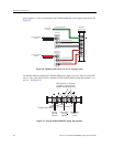
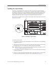
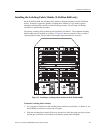


Installing the Hardware
72 Enterasys X-Pedition 8000/8600 Getting Started Guide
SSR-CM2B-64
SSR-CM3-128
SSR-CM4-256
E8.2.0.0
WA R N I N G : The SSR-CM4-256 is designed for
slots 0 and 1 only, and is easily damaged by
electrostatic discharge.
CAUTION: You cannot hot swap the Primary CM;
however, you may hot swap a Secondary CM by
pressing the hot swap button.
Note: You cannot use a CM4 with CM3 or CM2
command modules. Older modules will not
recognize the CM4.
Default Module Settings
The CM4 comes with the baud rate on RS232
console port set to 9600.
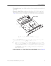
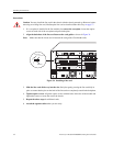
Preparing the Module
• You must install the PCMCIA card before you
install the command module. You cannot add or
remove a PCMCIA card while the unit is powered
on.
Proper Boot Sequence
• The HBT, ERR, and DIAG LEDs light momentarily.
• The screen displays the boot software version, cache,
and processor information.
• The CM boots an image if available or stops at a
prompt for configuration.
Common Errors
• The firmware image was loaded but no traffic is being
passed. This occurs when your network reboots and
cannot find your network settings in the configuration
file.
• Screen connected to console port displays random
text. Change terminal to 9600 baud/8 bits/Xon
Xoff/full duplex.
Helpful CLI Commands for Debugging
• System show hardware
• System show version
• System show bootlog
SSR-FDDI-02
3.2.0.0
Preparing the Module
• Before installing the module, you must install at
least one of the following FPHYs (purchased
separately): FPHY-01, FPHY-02, or FPHY-09.
See Installing FPHYs
on page 79.
• Because FDDI full duplex is not an industry
standard, its implementation is based on the
Digital Equipment Corporation (DEC) standard.
FDDI full duplex will interoperate with all DEC
products and most Enterasys Networks FDDI
products.
Proper Boot Sequence
• Firmware loads.
• The LEDs on Port 1 light in the following order: A, B,
P, S, Rx, and Tx. After the Tx LED lights, all LEDs
turn off and the online LED turns green.
• Diagnostic messages display for each line card.
• Status lights on line cards go online.
• Link lights activate for connected lines.
Common Errors
• The X-Pedition is not powered up.
• Ensure that the device attached to the module is
powered up and operating correctly.
• The module is not properly seated in the slot.
• Connectors on both ends of the cable are not properly
engaged. Fiber cable attached to an SC-type port did
not click into place or is not properly seated.
• If you are using fiber optic cable with an ST-type
connector in conjunction with an SC-ST port
converter, try switching the TX and RX connectors.
Helpful CLI Commands for Debugging
• System show hardware
• System show version
• System show bootlog
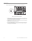
Table 19. Line card installation notes (Continued)
Minimum
Firmware
Restrictions Special Instructions