


EPSON Stylus PHOTO 810/820/830 Revision B
Disassembly and Assembly Disassembly 103
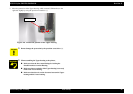
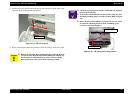
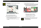
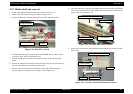
When assembling the LD pad on the Pad holder and the Hopper
pad on the Hopper,
Make sure to place it inside the square dent.
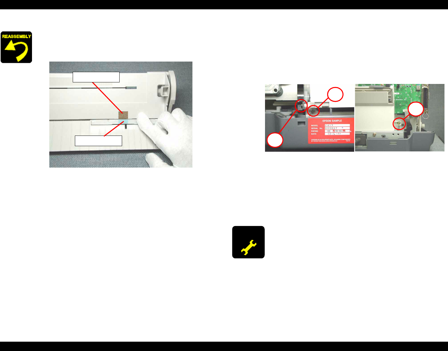
Figure 4-22. Hopper pad and LD pad setting position
Do not touch the surface of these pads.
Do not reuse the pad which you miss to stick.
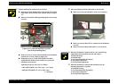
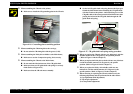
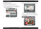
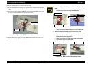
When assembling the Pad holder to the ASF frame,
Make sure to install the tip of the Torsion spring 29.1 in the
holes of the Pad holder and the ASF frame.
Make sure that the Pad holder (Paper return plate) moves
smoothly.
Hopper pad
LD pad
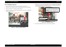
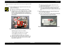
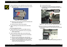
When assembling the ASF unit to the printer,
Make sure that the LD roller is set to the ASF home position.
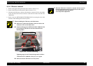
Fasten three screws (C.B.S. SCREW 3x6 F/Zn, C.B.S-TITE
(P4) 3x6 F/Zn, C.B.P-TITE 3x8 F/Zn) for securing the ASF
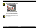
unit in the order indicated in the following figure.
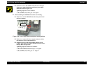
Figure 4-23. ASF fixing screws fastening order
Tightening torque for each screw is as follows.
•
C.B.S. SCREW, 3x6, F/Zn (1 pcs) : 9 ± 1 kgf.cm
• C.B.S-TITE (P4), 3x6, F/Zn (1 pcs) : 9 ± 1 kgf.cm
• C.B.P-TITE, 3x8, F/Zn (1 pcs) : 6 ± 1 kgf.cm
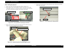
ADJUSTMENT
REQUIRED
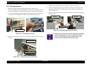
When the CR motor is removed or replaced with new one, the
following adjustment must be performed in the order below.
1) Top margin adjustment
2) 1st dot position adjustment
3
1
2