


EPSON Stylus PHOTO 810/820/830 Revision B
Operating Principles Electrical Circuit Operating Principles 54
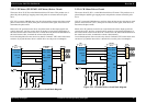
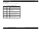
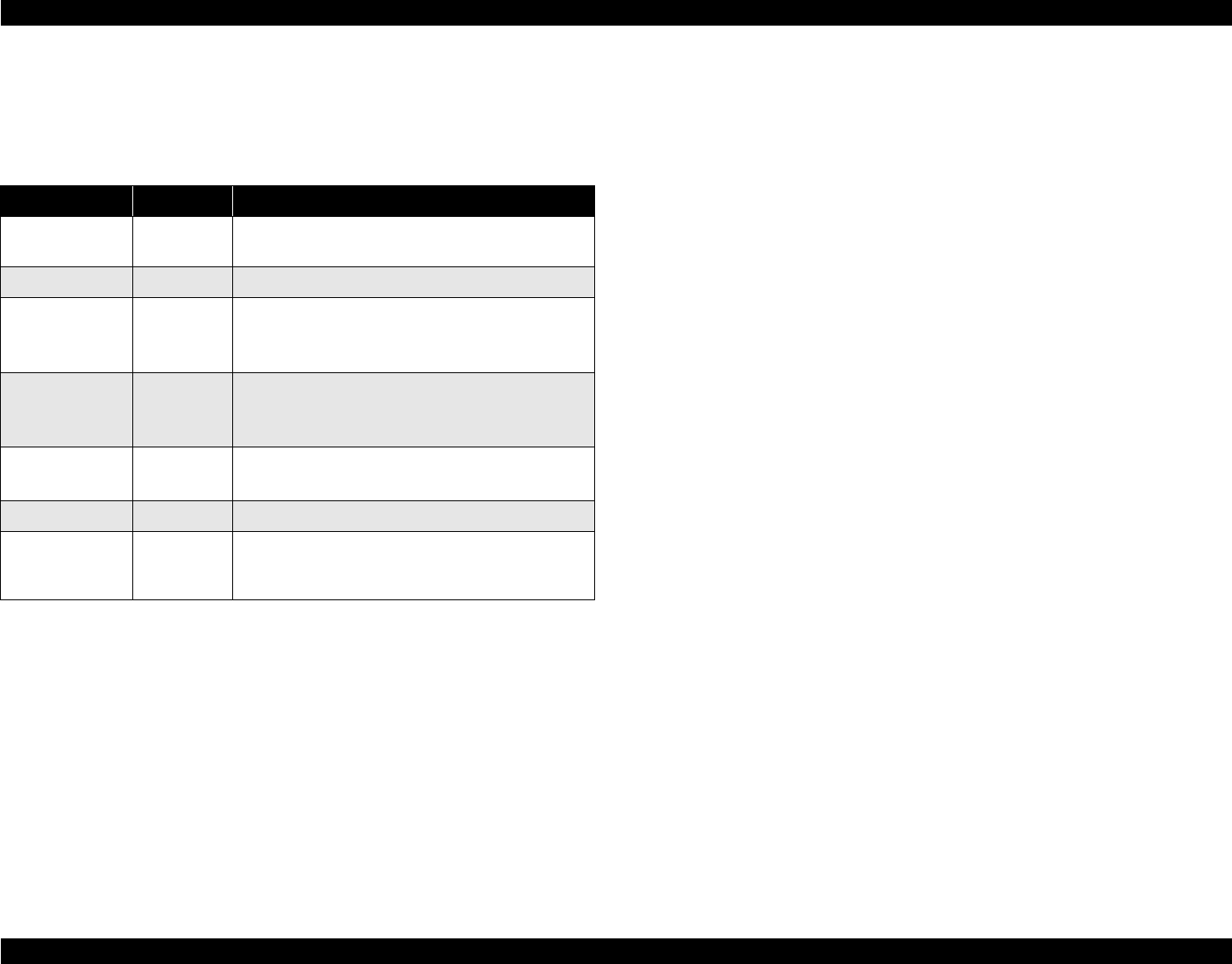
2.2.3.1 Main Elements
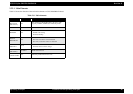
Table 2-10 shows the function of the each main elements on C483/C484 Main-B
board.
Table 2-10. Main elements (Stylus C61/C62)
IC Location Function
CPU
E01A37**/39**
IC8
CPU mounted on the MAIN board is driven by clock
frequency 48 MHz, 24MHz and controls the printer.
DRAM IC1/IC2 Bus= 16 bit, 4M/16Mbit DRAM
EEPROM IC5
1kbit EEPROM
• Default value setting
• Parameter backup
Reset Regulator IC
BN6150F-E2
IC3
Reset IC
• For +5V; reset when +4.2V is detected
• For +42V, reset when +35.8V is detected
Common Driver
E09A29LA
IC10
Head drive control HIC
• Generates head common voltage.
Motor Driver IC6 PF/CR motor drive IC
Parallel I/F IC
SN74LVCZ16128
4AGT
IC7 IEEE1284 parallel I/F transceiver IC.