


EPSON Stylus PHOTO 810/820/830 Revision B
Operating Principles Electrical Circuit Operating Principles 49
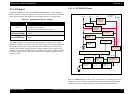
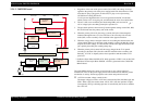
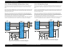
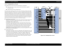
2.2.2.2 Printhead Driver Circuit
The printhead driver circuit consists of the following two components:
Head common driver circuit (Common driver IC19 & Wave amplifier
transistor Q2, Q3)
Nozzle selector IC on the printhead driver
The common driver (IC19) generates a basic drive waveform according to the output
signals from CPU (IC1). The basic drive waveform is amplified by the transistors Q2
and Q3 (the amplified one is called drive waveform.) and then transferred to the nozzle
selector IC on the printhead driver board. Print data is converted to serial data by the
CPU and then sent to the nozzle selector IC on the printhead driver board. Based on the
serial data, the nozzle selector IC determines the nozzles to be actuated. The selected
nozzles are driven by the drive waveforms amplified by the transistor Q2 and Q3. See
refer to Figure 2-19 for the printhead driver circuit block diagram.
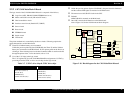
Head common driver circuit
The basic drive waveform is generated in the common driver (IC19) based on the
following 12 signal lines output from the CPU (IC1); A0-A4, CLK1, CLK2,
FLOOR, RST, DATA, DCLK, and E.
By the DATA signal output from the CPU, the original data for the basic drive
waveform is written in the memory in the common driver (IC19). The addresses
for the written data are determined by A0-A4 signals. Then, the necessary data is
selected from the address and appropriate basic drive waveform is generated.
Generated basic drive waveform is transferred to nozzle selector IC on the
printhead driver board through the transistor Q2 and Q3 and applied to the nozzle
PZT specified by nozzle selector IC.
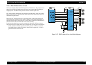
Nozzle selector circuit
Printing data is allocated to the six rows (the number of the head nozzle rows) and
converted into serial data by the CPU (IC1). Then the converted data is transferred
to the nozzle selector IC through the six signals lines (HS01 to HS06). Data
transmission from the CPU to the nozzle selector synchronizes with the LAT
signal and SCK clock signal. Based on the transmitted data, appropriate nozzle is
selected and the PZTs of the selected nozzle are driven by the drive waveform
output from the head common driver.
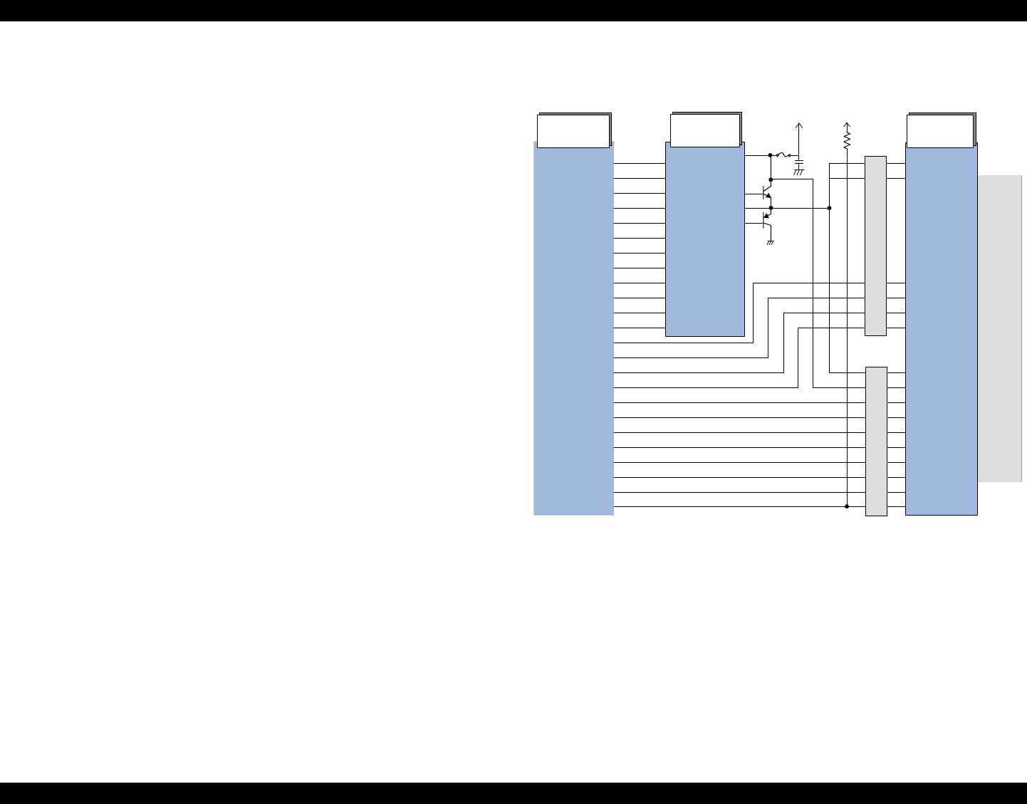
Figure 2-19. Printhead driver circuit
CPU
(IC1)
Common
Driver(IC19)
Nozzle
Selector IC
+4.2V
Head
Drive
Pulse
CN9
CN8
HWA0
HWA1
HWA2
HWA3
HWA4
HWCLK1
HWCLK2
HWFLR
HWRST
HWSDATA
HWSCLK
HWSLAT
HSOCLK
HCH
HSO1 ~ HSO6
HSOCMD
HLAT
HNCHG
C-P32
C-P13
C-P30
C-P34
C-P12
C-P40
COM
COM
SCK
CH
SI1 ~ SI6
SP
COM
VHV
LAT
NCHG
CSCK
COI
CRST
CSDA
CVDD
THM
AO
A1
A2
A3
A4
CLK1
CLK2
FLOOR
RST
DATA
DCLK
E
VCC45
NPNB
FB
PNPB
132
133
134
135
136
127
126
125
124
130
129
128
13
12
21
24
19
20
8
11
10
18
9
6
26
25
24
23
22
3
4
5
6
27
28
1
F1
+3.3V
19
17
15
14
Q2
Q3
15
13
11
9
2
1
2
4
8
6
10
11
12
14
15
13