


EPSON Stylus PHOTO 810/820/830 Revision B
Disassembly and Assembly Disassembly 112
CHECK
POINT
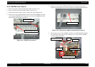
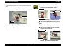
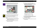
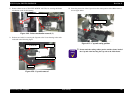
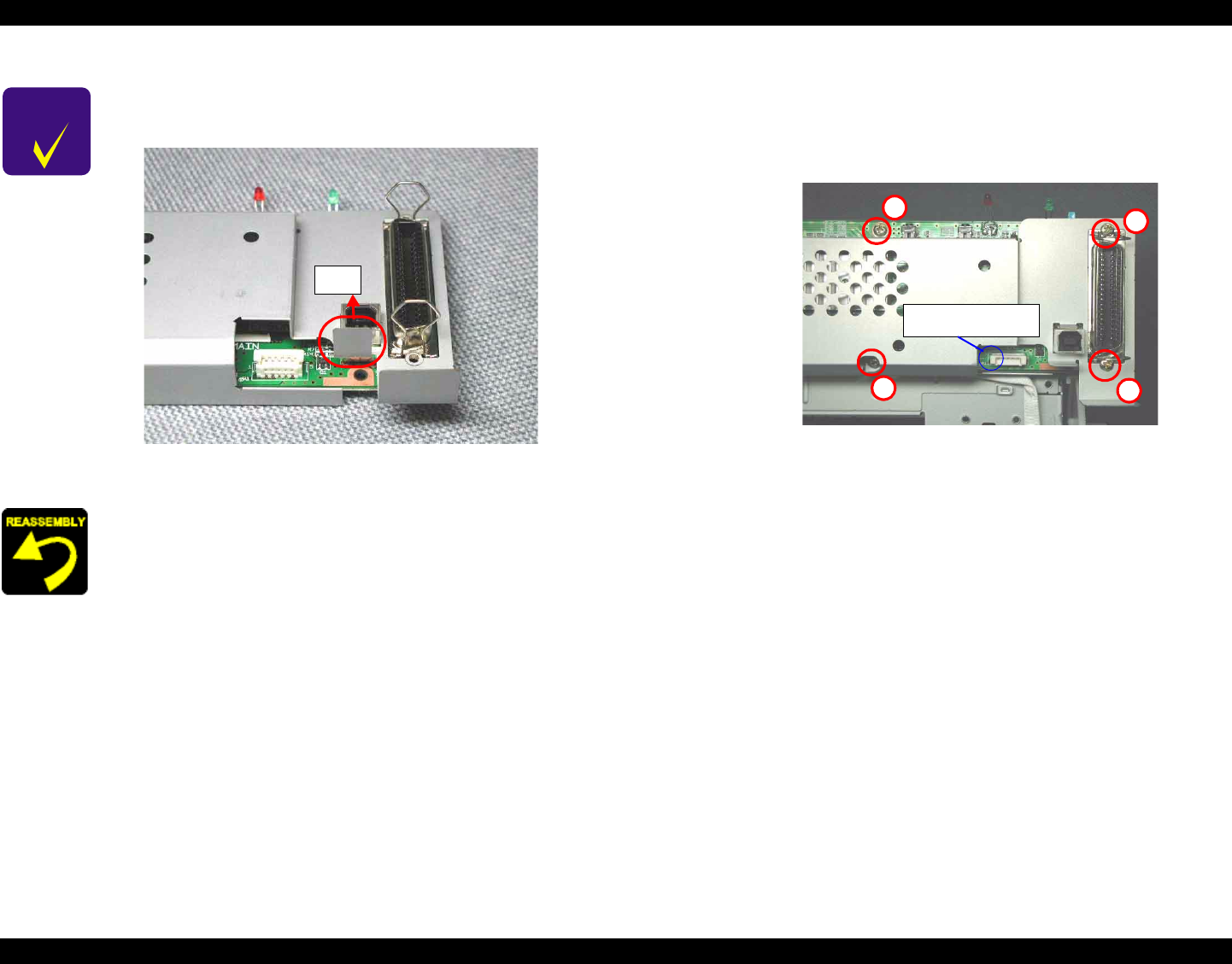
When removing the Main board shield plate from the Main
board, pull the part indicated below vertically and remove it.
Figure 4-43. Main board shield plate removal
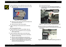
When assembling the Main board to the M/B mounting plate,
Make sure to set it to the M/B mounting plate correctly.
Do not touch the LED on the Main board
When assembling the Main board shield plate on the Main
board,
When the M/B mounting plate is removed from the Printer
mechanism, the hook of the M/B mounting plate deforms.
Therefore, you have to use new one.
Make sure that the metal fittings for locking the Parallel
interface is on its shield plate.
Pull
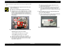
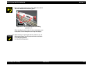
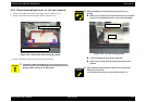
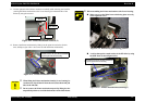
Fasten four screws (C.B.S. SCREW 3x6 F/Zn,
C.B.S. SCREW 3x14 F/Zn) for securing the Main board
shield plate and the Main board to the Main frame in the
order indicated in the following figure.
Figure 4-44. Circuit board assembling
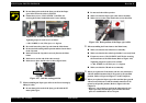
Tightening torque for each screw is as follows.
•
C.B.S. SCREW, 3x6, F/Zn (2 pcs)
: 9 ± 1 kgf.cm
•
C.B.S. SCREW, 3x14, F/Zn (2 pcs) : 9 ± 1 kgf.cm
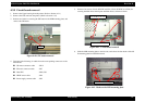
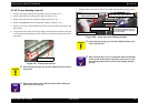
Make sure to connect all cables to the connectors (CN2, CN4,
CN7, CN8, CN9, CN12) on the Main board in the correct
direction. (Refer to Figure 4-44)
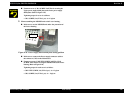
When assembling the SW button,
Make sure that two hooks of the SW button is correctly fixed
to the Main frame.
3
1
2
4
Blue line marking side
for P/S cable