


EPSON Stylus PHOTO 810/820/830 Revision B
Operating Principles Overview 38
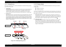
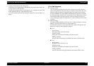
2. Wiper with the Cap unit
The wiping operation is controlled by the CR unit movement. This operation is
usually performed with every CL sequence which is to absorb the ink from the ink
cartridge, the ink cavity by the Pump unit. Following figure shows you the
mechanism for the wiping operation.
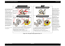
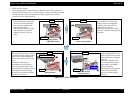
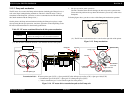
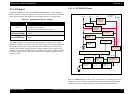
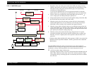
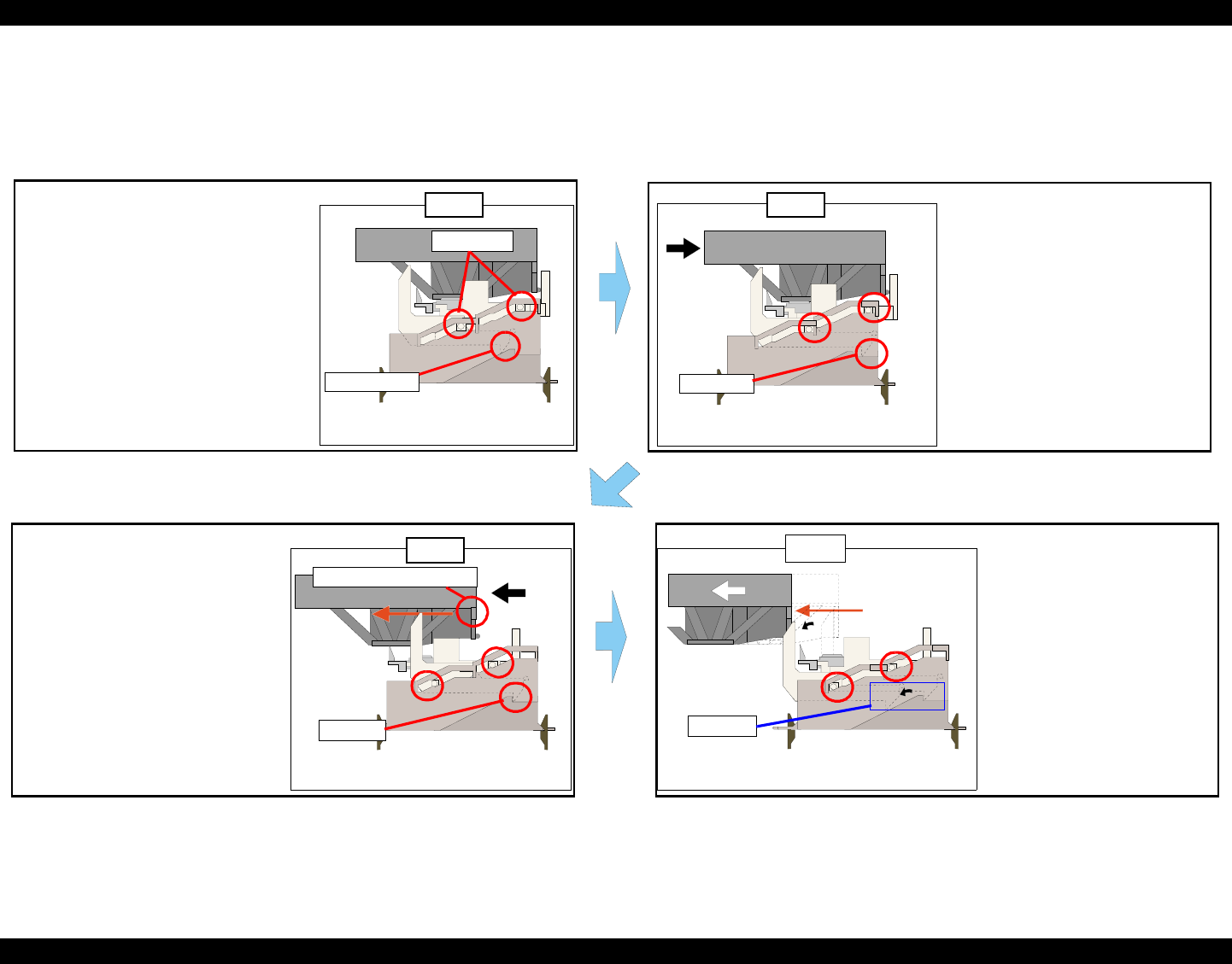
Figure 2-12. Wiper mechanism
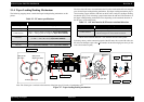
The CR unit moves to the wiper
setting position on the rightmost
position of the Cap frame with
keeping the cap covered.
In this time, the hook of the Slider
lock lever is latched to the dent of the
Cap frame.
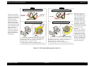
When the wiping operation is
finished and the CR unit moves
further to the left side, the hook
of the CR unit hits to the Slider
lock lever.
In this time, the Slider lock
lever is released and the Cap
slider returns to the bottom
position completely.
(The broken line is the position
of the CR unit & the Slider
lock lever just before being
released.)
When the CR unit moves to the left
side from the wiper setting position,
the Cap unit is pulled back by the
tension force of the
Extension spring
0.523
.
In this time, the Cap unit is
automatically set to the wiping
position because the hook on the
Slider lock lever is latched to dent of
the Cap frame. And, the wiping
operation is performed according to
the CR unit movement.
Wiping position
Step 2
Wiper setting position
Released position
(Bottom position)
Step 4
Step 1
Step 3
Capping position
(CR home position)
When the CR unit is in the home
position, the hook of the Slider
lock lever is not latched to the
dent of the Cap frame.
In this time, the protrusion of the
Cap slider does not reach the
rightmost position of the Cap
frame.
Protrusion
Not latched
Latched
Latched
Released
Protrusion of the CR unit