


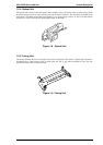

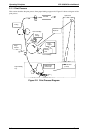
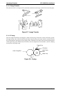
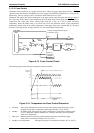

2.1.1.3 Laser Exposure
The laser beam, emitted from the optical unit, makes an invisible static image. The SOS (start of scan)
sensor, installed on the laser diode control board (PWB-D), unifies the laser emission timing for each scan
line.
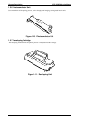
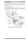
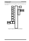
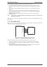
2.1.1.4 Development
Toner is applied to the invisible static image on the PC drum and a toner image is created on the surface.
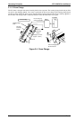
When the PC drum starts to rotate (when the main motor is activated), the PC drum surface remains 0 V at
the position between the rotating charge brush and sleeve roller. At this time, a specified positive voltage is
applied to the sleeve roller to prevent toner from being attracted back onto the PC drum (reverse bias
control).
1. Toner hopper: Contains toner.
2. Toner agitating screw:Stirs the toner in the hopper and sends the toner to the toner transport
roller.
3. Toner transport roller:Transports the toner to the sleeve roller.
4. Doctor blade: Spreads a thin, even coat of toner over the resin sleeve. The toner is
negatively charged by passing between this blade and resin sleeve.
5. Sleeve roller: Rotates the resin sleeve.
6. Resin sleeve: Carries the toner to the PC drum surface for development.
7. Bias seal: Collects the toner remaining on the resin sleeve.
8. PC drum: Is exposed to the laser to create an invisible image and rotates to carry
the developed image to the paper surface.
Charged Surface
Laser-Exposed Surface:
(Approx. -50 V)
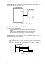
PWB-D
SOS Sensor
Reflector Mirror
Laser Diode
M2
CN210
CN205
C180 MAIN
IC201
1
5
1
7
Figure 2-5. Laser Exposure
2
4
3
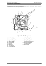
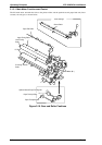
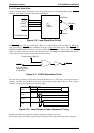
Vs Terminal
VB TerminalVBL Terminal
VB (Developing Bias)
VBL (Toner Blade Bias)
Vs (Lower Seal Bias)
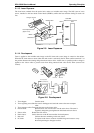
PWB-F
CN1F
CN204
C180 MAIN
IC201
1
8
1
8
Figure 2-6. Development
EPL-5500W Service Manual Operating Principles
Rev. A 2-5