


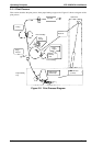
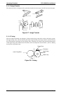
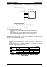
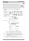
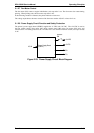

2.1.2.3 Fuser Control
The heater lamp, powered by AC voltage, heats the fuser. When the power supply board receives a FUSER
signal from the main board (C180 MAIN), the power supply board (PWB-E) supplies the AC voltage to the
heater lamp. This AC voltage is cut by an interlock switch when the case is open.
Thermistor TH1 detects the surface temperature of the upper fusing roller and inputs that analog voltage to
the 77-pin chip, IC201. Based on this temperature data, the heater lamp on/off signal (the
FUSER signal) is
output from the 54-pin chip, IC201, causing heater lamp H1 to turn on or off to control the fusing
temperature. When the heater lamp is not turned off even if the thermistor detects a high temperature
malfunction (which occurs if the surface temperature of the upper fusing roller exceeds 200º C), the signal
from the 75-pin chip, IC201, changes from H to L to turn off the heater lamp forcibly.
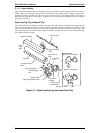
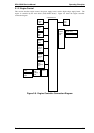
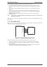
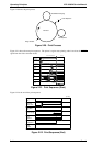
The following figure shows the fuser temperature control procedure.
1. Warm up: After printer initialization, printer warm up starts, and the heater lamp turns on until
the upper fusing roller’s temperature reaches approximately 172º C (342º F).
2. Standby: In standby mode, the upper fusing roller’s temperature is controlled to maintain 156º C
(313º F). When this condition continues for 3 minutes, the printer goes into standby
mode at low temperature.
3. Print cycle: When the printer receives the printing command from the controller, the upper
fusing roller is controlled to maintain 172º C (342º F).
4. Standby at low temperature: The upper fusing roller is controlled to maintain 112º C (234º F).
C180 MAIN
IC201
77
54
75
Analog Voltage Detected by the
Thermistor (TH1)
5 VDC
L
H
IC202B
5
6
4
L
H
H
H
2
3
1
IC202A
4
3
L
L
H1:ON
H
H1:OFF
1
2
1
5
1
5
TH1
Thermistor
PWB-E
1
2
3
H1
TF1
Heater Lamp
Thermal Fuse
Heater Lamp
ON/OFF Signal
CN202
CN207
CN1E
CN3E
Figure 2-13. Fuser Control Circuit
Temperature
(Degrees C)
172
156
112
Power On
Warm up Standby Standby with Low
Temperature
Time
When a print is made immediately after warm up
Figure 2-14. Temperature for Fuser Control Procedure
Operating Principles EPL-5500W Service Manual
2-10 Rev. A