


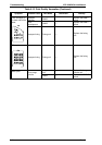


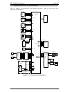
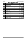
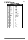
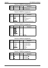


A.1 CONNECTOR PIN ASSIGNMENTS
Figure A-1 illustrates the interconnection of the primary components. Table A-1 gives the size and a
description of each connector.
1
2
3
4
M1
Main Motor
5
4
3
2
M2
Polygon Motor
1
2
3
4
1
CN1M
CN206
ϕ
A
ϕ
A
ϕ
B
ϕ
B
POLYGON CTL
5 VDC
GND
24 VDC
NC
1
2
M3
Fan Motor
CN211
FAN
24 VDC
CN210
1
2
3
1
2
3
CN3S
ANODE (PC1)
GND
PC3
PC3
CN208
Paper Exit Sensor
1
2
3
1
2
3
CN1S
ANODE (PC1)
GND
PC1
PC1
CN203
Paper Take-up Sensor
4
5
6
NC
24 VDC
FEED1
SL1
1
21
2
Paper Take-up
Solenoid
CN2S
Fusing Roller
Thermistor
TH1
1
2
THERMISTOR
5 VDC
CN202
1
2
3
HV C
HV T
HV SEL1
4
5
6
HV SEL2
HV B
BIAS MON
7
8
1
2
3
4
5
6
7
8
PWB-S
8
7
6
5
4
3
2
1
CN204
PWB-F
High
Voltage
Unit
8
7
6
5
4
3
2
1
GND
24 VDC
CN1F
Image
Transfer
Housing
Image
Transfer
Charger
1
2
3
24 VDC
FEED2
NC
4
5
6
5 VDC
GND
P EMP2
7
8
PSIZE0
2NDBIN
9
10
mm/inches
UNIVERSAL
11
8
CHECK1
PWB-A
8
7
6
5
4
3
2
1
CN1A
12
11
10
9
CN209
1
2
SL2
Paper Take-up
Solenoid
24 VDC
FEED2
2nd Paper Feeding
Unit (Optional)
CHECK2
7
6
5
4
3
2
1
1
2
3
4
5
6
7
PWB-D
CN205
CN1D
Laser Diode
Drive Board
1
2
3
4
5
1
2
3
4
5
DC5V
L DATA
GND
LD APC1 (LDVR1)
LD APC1 (LDVR2)
CO
S SCAN
CN207
PWB-E
1
2
3
H1
TF1
Fusing Roller
Heater Lamp
Fusing Roller Thermal Fuse
CN1E
CN3E
24 VDC
GND
GND
5 VDC
FUSER LAMP
Interlock
Switch
Inlet
Board
Power SW
Inlet
Power
Unit
HEAT N
NC
HEAT L
C180 MAIN
Board
HOST
PC
CN2
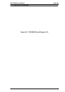
Figure A-1. Connector Connections
EPL-5500W Service Manual Appendix
Rev. A A-1