


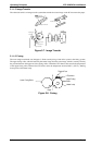


2.1.2.5 Laser Diode Drive
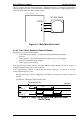
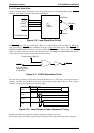
Figure 2-16 shows the laser diode drive circuit. Laser diode emission is controlled by three signals (LDATA,
LDAPC1, and LDAPC2) from the main board (C180 MAIN).
The
LDATA signal is the laser on/off signal. When it is LOW, the laser emits, and when it is HIGH, the
laser stops emitting.
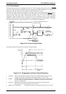
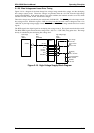
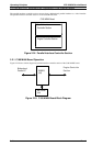
LDATA is the combination of the two signals in the figure below. If the VIDEO or the
FORCED LASER DIODE ON signal is activated (LOW), the
LDATA signal will be active. The VIDEO
signal is an image signal sent from the video controller circuit. The FORCED LASER DIODE ON signal is
a laser emission signal to apply the laser beam to the SOS sensor.
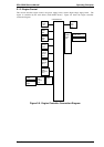
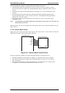
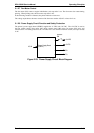
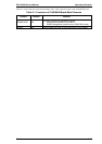
The laser diode is forcibly activated after scanner motor M2 turns on. At this time, laser emission power is
adjusted. LDAPC1 and LDAPC2 are the laser emission power adjust signals; they are analog signals.
LDAPC1 is a tuning, and LDAPC2 is a fine tuning signal.
If either of the following conditions is detected, the printer indicates a laser error:
The LDAPC1 signal or LDAPC2 signal has been out of the specified range while laser power is adjusted.
SSCAN
LD_CTL
LDAPC1
LDAPC2
L DATA
C180 MAIN Board
LD
SOS
(PWB-D)
Laser Diode
SOS Sensor
SOS Mirror
Figure 2-16. Laser Diode Drive Circuit
L DATA
Forced Laser Diode ON
VIDEO
from the Video
Controller Circuit
(C180 MAIN)
Figure 2-17. LDATA Generation Circuit
Scanner Motor On
LDATA
LDAPC1
LDAPC2
P_CTL
Figure 2-18. Laser Emission Power Adjustment Timing
Operating Principles EPL-5500W Service Manual
2-12 Rev. A